GE Multilin C60 Breaker Protection System B-51
APPENDIX B B.4 MEMORY MAPPING
B
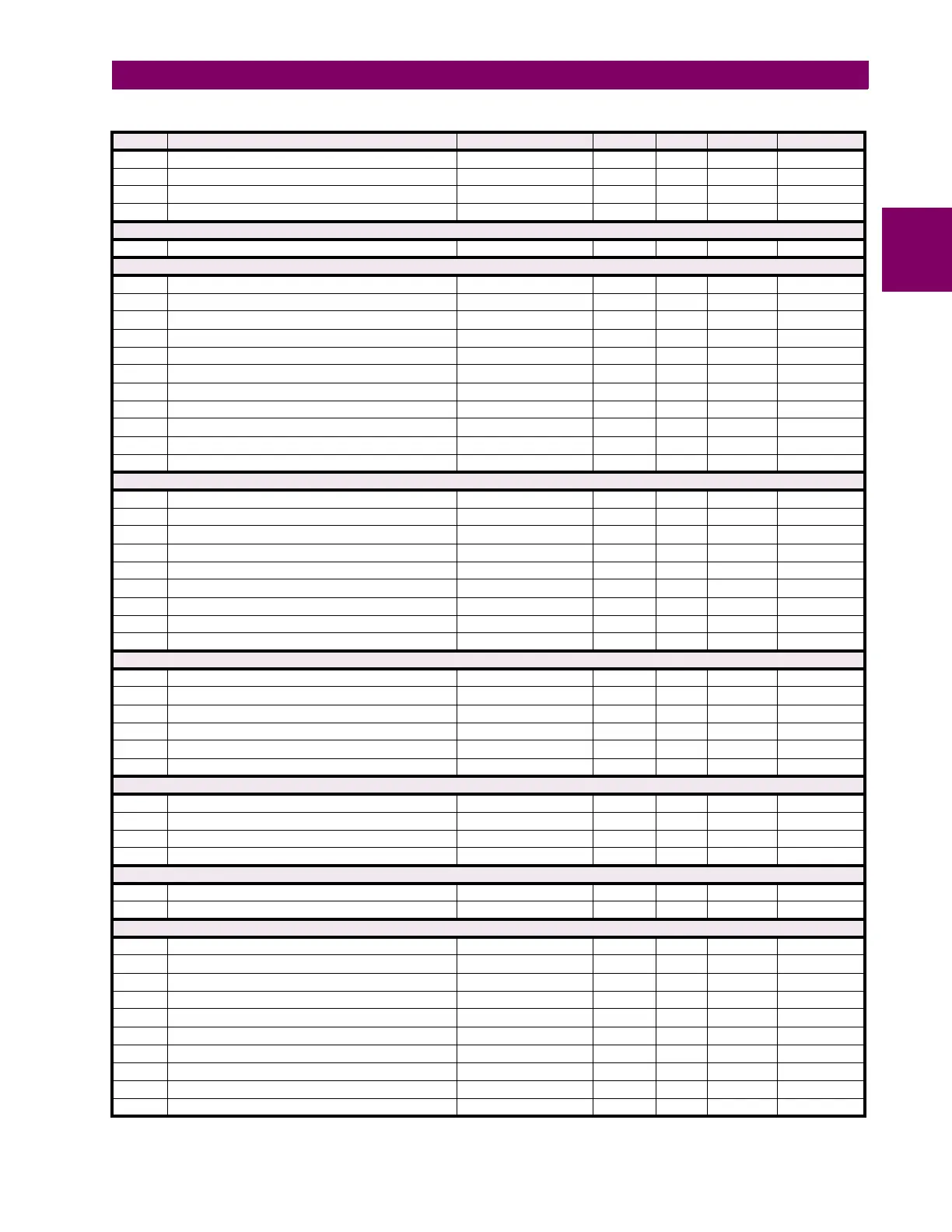
993D Breaker Restrike 1 Target 0 to 2 --- 1 F109 0 (Self-reset)
993E Breaker Restrike 1 Events 0 to 1 --- 1 F102 0 (Disabled)
993F Reserved (2 items) --- --- --- F002 0
9941 ...Repeated for Breaker Restrike 2
Teleprotection Inputs/Outputs Commands (Read/Write Command)
9980 Teleprotection Clear Lost Packets 0 to 1 --- 1 F126 0 (No)
Teleprotection Inputs/Outputs (Read/Write Settings)
9990 Teleprotection Function 0 to 1 --- 1 F102 0 (Disabled)
9991 Teleprotection Number of Terminals 2 to 3 --- 1 F001 2
9992 Teleprotection Number of Channels 1 to 2 --- 1 F001 1
9993 Teleprotection Local Relay ID 0 to 255 --- 1 F001 0
9994 Teleprotection Terminal 1 ID 0 to 255 --- 1 F001 0
9995 Teleprotection Terminal 2 ID 0 to 255 --- 1 F001 0
9996 Reserved (10 items) 0 to 1 --- 1 F001 0
9A00 Teleprotection Input 1-n Default States (16 items) 0 to 3 --- 1 F086 0 (Off)
9A10 Teleprotection Input 2-n Default States (16 items) 0 to 3 --- 1 F086 0 (Off)
9A20 Teleprotection Output 1-n Operand (16 items) 0 to 4294967295 --- 1 F300 0
9A40 Teleprotection Output 2-n Operand (16 items) 0 to 4294967295 --- 1 F300 0
Teleprotection Channel Tests (Read Only)
9AA0 Teleprotection Channel 1 Status 0 to 2 --- 1 F134 1 (OK)
9AA1 Teleprotection Channel 1 Number of Lost Packets 0 to 65535 --- 1 F001 0
9AA2 Teleprotection Channel 2 Status 0 to 2 --- 1 F134 2 (n/a)
9AA3 Teleprotection Channel 2 Number of Lost Packets 0 to 65535 --- 1 F001 0
9AA4 Teleprotection Network Status 0 to 2 --- 1 F134 2 (n/a)
9AAF Teleprotection Channel 1 Input States 0 to 1 --- 1 F500 0
9AB0 Teleprotection Channel 2 Input States 0 to 1 --- 1 F500 0
9AC0 Teleprotection Input 1 States, 1 per register (16 items) 0 to 1 --- 1 F108 0 (Off)
9AD0 Teleprotection Input 2 States, 1 per register (16 items) 0 to 1 --- 1 F108 0 (Off)
VT Fuse Failure (Read/Write Setting) (4 modules)
A09A VT Fuse Failure1 Function 0 to 1 --- 1 F102 0 (Disabled)
A09B VT Fuse Failure Neutral Wire Open1 Function 0 to 1 --- 1 F102 0 (Disabled)
A09C VT Fuse Failure Neutral Wire Open 1 3rd Harmonic Pickup 0 to 3 pu 0.001 F001 100
A09D ...Repeated for module number 2
A0A0 ...Repeated for module number 3
A0A3 ...Repeated for module number 4
VT Fuse Failure Actuals (Read Only) (4 modules)
A0AC VT Fuse Failure 1 V0 3rd Harmonic 0 to 999999.999 V 0.001 F060 0
A0AE ...Repeated for module number 2
A0B0 ...Repeated for module number 3
A0B2 ...Repeated for module number 4
Selector Switch Actual Values (Read Only)
A210 Selector Switch 1 Position 1 to 7 --- 1 F001 0
A211 Selector Switch 2 Position 1 to 7 --- 1 F001 1
Selector Switch Settings (Read/Write) (2 modules)
A280 Selector 1 Function 0 to 1 --- 1 F102 0 (Disabled)
A281 Selector 1 Range 1 to 7 --- 1 F001 7
A282 Selector 1 Timeout 3 to 60 s 0.1 F001 50
A283 Selector 1 Step Up 0 to 4294967295 --- 1 F300 0
A285 Selector 1 Step Mode 0 to 1 --- 1 F083 0 (Time-out)
A286 Selector 1 Acknowledge 0 to 4294967295 --- 1 F300 0
A288 Selector 1 Bit0 0 to 4294967295 --- 1 F300 0
A28A Selector 1 Bit1 0 to 4294967295 --- 1 F300 0
A28C Selector 1 Bit2 0 to 4294967295 --- 1 F300 0
A28E Selector 1 Bit Mode 0 to 1 --- 1 F083 0 (Time-out)
Table B–10: MODBUS MEMORY MAP (Sheet 43 of 66)
ADDR REGISTER NAME RANGE UNITS STEP FORMAT DEFAULT