3-4 C60 Breaker Protection System GE Multilin
3.1 DESCRIPTION 3 HARDWARE
3
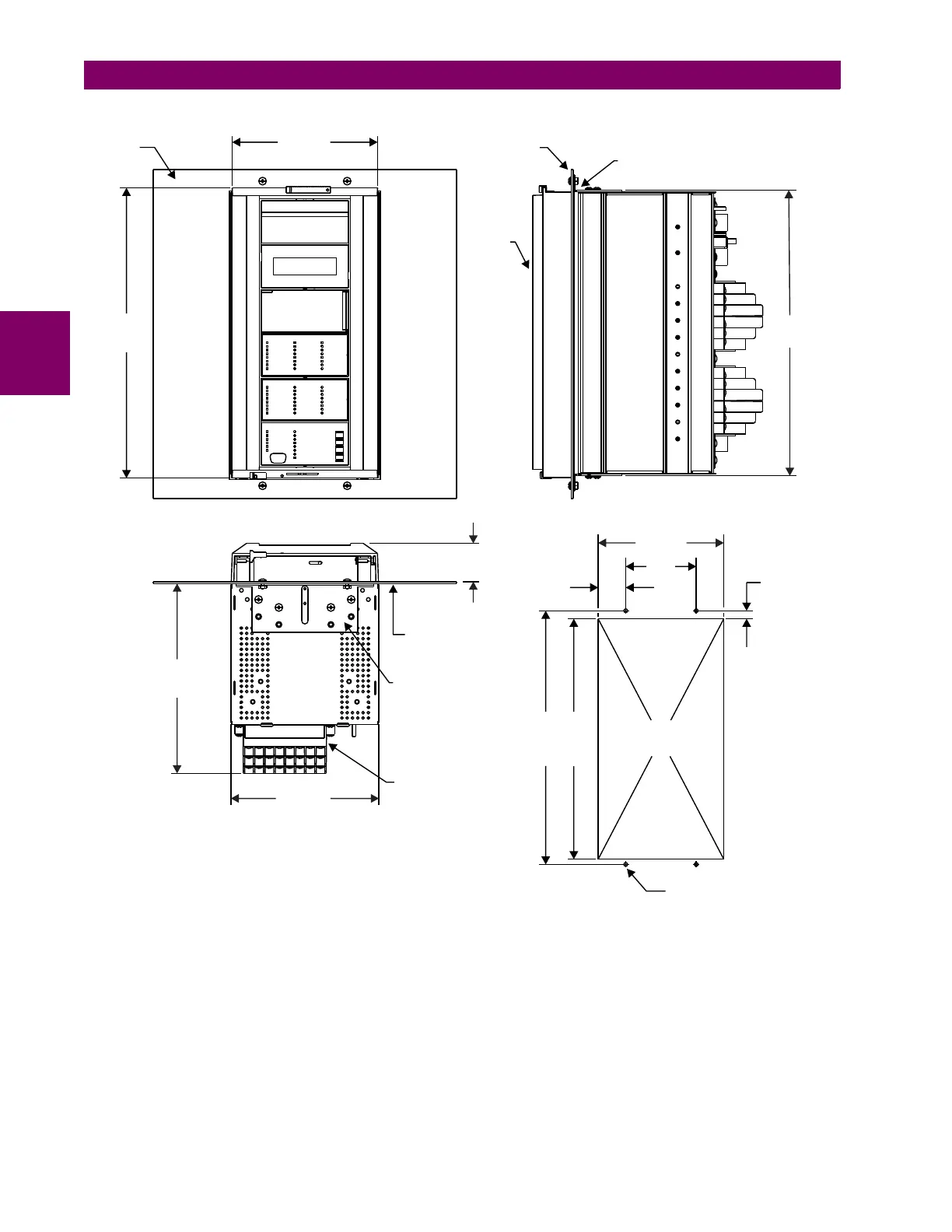
Figure 3–5: C60 VERTICAL MOUNTING AND DIMENSIONS (STANDARD PANEL)
For side mounting C60 devices with the enhanced front panel, see the following documents available on the UR DVD and
the GE Grid Solutions website:
• GEK-113180: UR-Series UR-V Side-Mounting Front Panel Assembly Instructions
• GEK-113181: Connecting a Remote UR-V Enhanced Front Panel to a Vertical UR Device Instruction Sheet
• GEK-113182: Connecting a Remote UR-V Enhanced Front Panel to a Vertically-Mounted Horizontal UR Device
Instruction Sheet
For side mounting C60 devices with the standard front panel, use the following figures.
13.72"
(348.5 mm)
7.00"
(177.8 mm)
13.50"
(342.9 mm)
Front of
panel
Front
bezel
Panel
Mounting bracket
1.57”
(39.9 mm)
4.00
(101.6)
7.13”
(181.1 mm)
0.46”
(11.7 mm)
13.65”
(346.7 mm)
14.40”
(365.8 mm)
0.213" (5.4 mm),
4 places
Vertical front view
Vertical side view
843755A4.CDR
Vertical panel mounting
1.85"
(47.0 mm)
9.00"
(228.6 mm)
7.00"
(177.8 mm)
Terminal blocks
Mounting bracket
Panel shown for
reference only
Vertical bottom view