3-12 C60 Breaker Protection System GE Multilin
3.2 WIRING 3 HARDWARE
3
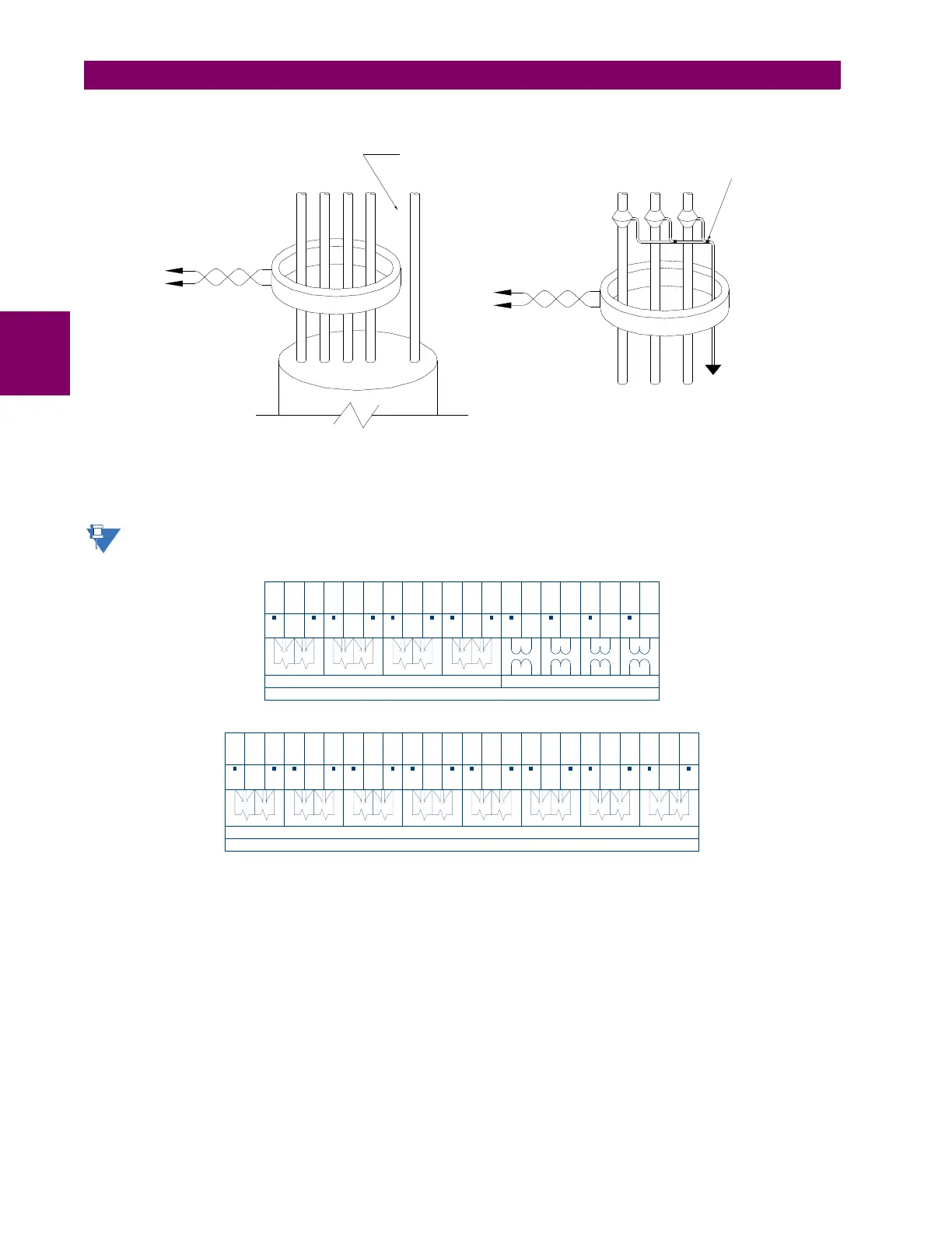
Figure 3–12: ZERO-SEQUENCE CORE BALANCE CT INSTALLATION
The phase voltage channels are used for most metering and protection purposes. The auxiliary voltage channel is used as
input for the synchrocheck and volts-per-hertz features.
Substitute the tilde “~” symbol with the slot position of the module in the following figure.
Figure 3–13: CT/VT MODULE WIRING
Ground connection to neutral
must be on the source side
UNSHIELDED CABLE
LOAD
ABCN G
Ground
outside CT
Source
LOAD
SHIELDED CABLE
996630A6.CDR
ABC
Source
To ground;
must be on
load side
Stress cone
shields
~
~
~
~
~
~
~
~
~
~
~
~
~
~
~
~
~
~
~
~
1a
1b
1c
2a
2b
2c
3a
4a
5a
6a
7a
8a
3b
4b
5c
6c
7c
8c
3c
4c
Current inputs
8F, 8G, 8L, and 8M modules (4 CTs and 4 VTs)
Voltage inputs
VA
VB
VC
VX
VA
VB
VC
VX
IA
IC
IB
IG
IA5
IC5
IB5
IG5
IA1
IC1
IB1
IG1
~
~
~
~
~
~
~
~
~
~
~
~
~
~
~
~
~
~
~
~
~
~
~
~
1a
5a
1b
5b
1c
5c
2a
6a
2b
6b
2c
6c
3a
7a
4a
8a
3b
7b
4b
8b
3c
7c
4c
8c
Current inputs
842766A3.CDR
IA
IA
IC
IC
IB
IB
IG
IG
IA5
IA5
IC5
IC5
IB5
IB5
IG5
IG5
IA1
IA1
IC1
IC1
IB1
IB1
IG1
IG1
8H, 8J, 8N, and 8R modules (8 CTs)