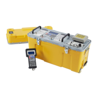
Druck ADTS 405 Service Manual
K0171 Issue No. 1 Page 2-5
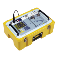
Altimeter Encoder Interface PCB (Figure 2-1)
13. The altimeter encoder interface PCB locates on a connector in the motherboard. Release the two
clips and disconnect the ribbon connector on the top edge of the PCB.
14. Unscrew and remove the two screws and plain washers securing PCB bracket to rear panel.
Carefully remove the PCB.
ARINC 429 Interface PCB (Figure 2-1)
15. The ARINC 429 interface PCB locates on a connector in the motherboard. Release the two clips
and disconnect the ribbon connector on the top edge of the PCB.
16. Unscrew and remove the two screws and plain washers securing PCB bracket to rear panel.
Carefully remove the PCB.
Front Panel (Figure 2-2)
17. To gain access to other components, lower the front panel as follows:
Note: This procedure does not completely remove the front panel.
18. Disconnect the ribbon cable connector from top edge of IEEE 488 interface PCB.
19. Invert the rack, unscrew and remove the five screws and shake proof washers securing base
plate to front panel along front edge of base plate. Restore rack to the correct way up.
20. Unscrew and remove the four screws securing front panel to rear chassis. These are located
above and below each handle.
21. Carefully lower the front panel until it is in a horizontal position on the bench.
22. Start to carefully separate the front panel from the chassis and disconnect the ribbon cable from
the mimic panel.
Mimic Panel
23. Unscrew and remove the seven nyloc nuts and plain washers securing the mimic panel to the
front panel. Remove the mimic panel.
Controller/Manifold Assembly (Figures 2-2 and 2-3)
Caution: Ensure absolute cleanliness of the work area for the following procedure to prevent
ingress of dirt into manifold.
24. Tilt the front panel to the vertical position and rest against rear chassis. Remove blanking caps
from Ps and Pt output fittings.
25. Unscrew and remove the two screws from each output fitting and remove fittings, rotating
slightly to ease removal.
26. Unscrew and remove the two screws from under output fittings securing manifold to front panel.
Lower front panel to horizontal position.
 Loading...