Do you have a question about the GE Druck DPI 610 and is the answer not in the manual?
Read safety instructions and ATEX certificate before operating the instrument.
Instructions for using the intrinsically safe calibrator in hazardous areas.
Condition regarding the 500V r.m.s. electric field strength test.
Output parameters for external measurement connectors.
Safe input parameters for various instrument sockets.
Maximum safe working pressures for different ranges.
Details on non-linearity, hysteresis, and repeatability.
Voltage and current input/output ranges, accuracy, and resolution.
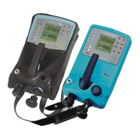
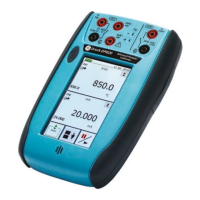
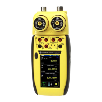
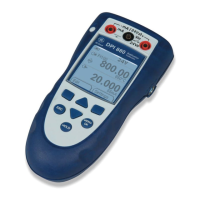
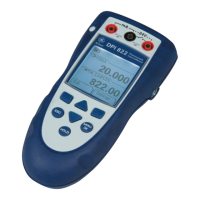
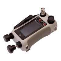
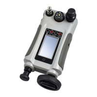
Description of instrument controls and key-pad layout.
Detailed explanation of each hard key's function and page reference.
Description of soft keys F1, EXIT, and F2 and their uses.
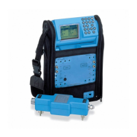
Diagrams and descriptions of electrical system connections.
Key features and capabilities of the instrument.
Maximum measurement input ratings not to be exceeded.
Explanation of cursor keys for navigation and selection.
Diagram and procedure for a P-V calibration setup.
Connecting for voltage and current measurements.
Using the TASK key to select test configurations.
Setting up test parameters manually in Cal Mode.
Procedure for performing pressure to current transmitter measurements.
Procedure for measuring pressure converter performance.
Procedure for I-P converter testing.
Simulating transmitter outputs for testing.
Procedure for testing relief valve operation.
Using P-DISPLAY for data logging pressure readings.
Procedure for performing leak tests on systems.
Procedure for performing pressure to voltage transmitter measurements.
Procedure for testing pressure switches.
Procedure for P-Display task.
Procedure for Leak Test task.
Tare reading to zero or a manual value.
Automatic data logging at set intervals.
Manually logging data points.
Instrument calibration, period, and requirements.
Step-by-step guide to calibrate the internal pressure sensor.
Procedure for calibrating the 5V input range.
Procedure for calibrating the 30V input range.
Procedure for calibrating the 55mA input range.
Procedure for calibrating the 24mA output range.
Procedure for calibrating the ambient temperature sensor.
Procedure for calibrating external pressure sensors.
Steps to compare readings with a standard.
Adjusting zero and full-scale calibration.
Best practices for calibration environment and process.
List of test equipment for calibration.
Critical safety precautions for hydraulic fluid handling.
Procedure for priming and bleeding air from the hydraulic system.
| Display | Backlit LCD |
|---|---|
| Operating Temperature | -10 to 50 °C (14 to 122 °F) |
| Measurement Parameters | Pressure, Current, Voltage, Temperature, Frequency |
| Pressure Accuracy | Up to 0.025% FS |
| Voltage Range | 0 to 30 V |
| Current Measurement Accuracy | 0.01% FS |
| Voltage Measurement Accuracy | 0.01% FS |
| Power Supply | Rechargeable battery or external power supply |
| Communication Interface | RS232 |
| Pressure Media | Compatible with non-corrosive gases and liquids |