Do you have a question about the GE Druck PC6-IDOS and is the answer not in the manual?
Identifies the device as Druck PC6-IDOS and the manual version K0354.
Indicates the manufacturer as GE Sensing.
Describes the calibrator's purpose, features, and benefits for testing.
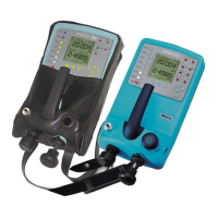
Differentiates between the PC6-IDOS Calibrator and Indicator models.
Warns about the dangers of uncontrolled high pressure release.
Provides warnings for rechargeable Ni-MH batteries regarding disposal and handling.
Explains the device keys, menu selection, and data entry procedures.
Details the procedure for using the tare function to zero the pressure reading.
Lists pressure ranges, accuracy, units, and overload specifications.
Details V/mA input/output, RS232 parameters, and display resolution.
Provides physical dimensions, weight, battery life, and system requirements.
Lists PC system requirements and product ordering codes.
Offers instructions for cleaning and basic maintenance.
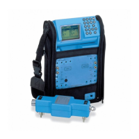
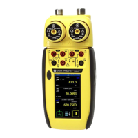
Introduces the calibrator as a portable, precision instrument.
Describes the device's housing, carry handle, display, and keypad.
Details the six-button keypad and its basic operation.
Explains the LCD's features, capacity, and display layout.
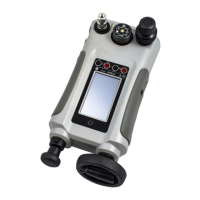
Describes the six sockets on the front panel for I/O and status.
Details sockets on the rear for EPM, RS232, and charger.
Illustrates the front panel layout including LCD, keypad, and connections.
Illustrates the rear panel layout for pressure, RS232, and power connections.
Covers unit selection, Max/Min display, Tare, and V/mA measure functions.
Explains Leak Test and file operations like View, Export, Import, Delete.
Procedure for setting high and low pressure warning limits.
Configuration for Zero, FS, Text, and Root in Measure mode.
Configuration for Range, Convert, P to V/mA, and Setup in Source mode.
Settings for voltage output, backlight, resolution, and event logging.
Configuration for log status and RS232 communication parameters.
Device configuration settings for date, language, zero, port, and power.
Procedure for adjusting the span of the pressure sensor.
Accessing calibration history and device serial numbers.
Downloading languages and managing user-defined units.
Provides an overview of the operations section.
Details connections for EPM, voltage/current inputs, and wiring.
Covers switch test setup and RS232 interface specifications.
Explains battery charging and voltage sourcing capabilities.
Details memory errors and how parameters are retained.
Explains messages like Tare, Max/Min, Overload, and Low Battery.
Covers switch state change, printer busy, and outside alarm warnings.
Explains display hold, connection faults, and short detected errors.
Provides explanations for various symbols displayed on the LCD.
Procedure for changing units and displaying Max/Min values.
Details the Tare function and V/mA measurement modes.
Explains Actual, Converted, and P to V/mA source modes.
Describes how to use the nudge function for source output adjustment.
Step-by-step guide to conducting a leak test.
Procedure for setting the duration of the leak test.
Introduces file operations: View, Export, Import, Delete.
Explains how to access and navigate stored files.
Procedures for exporting and importing calibration files.
Details how to delete individual files or all logged files.
Step-by-step guide to setting high and low pressure alarm limits.
Adjustments for Zero, Full Scale, Text, and Root functions in measure mode.
Configuration for source range, conversion, and P to V/mA.
Settings for output status, square root function, and step increments.
Configuration for ramp rate and dwell time.
Explains the operation of Ramp and Step modes.
Describes the nudge function for fine adjustment of source output.
Controls for voltage output and backlight settings.
Settings for measurement resolution and event logging triggers.
Steps for creating, logging to, viewing, and deleting log files.
Enabling/disabling logging and selecting files for operation.
Procedures for deleting individual or all logged files.
Enabling or disabling the logging function.
Configuration for RS232 status, baud rate, and stop bits.
Setting the device's date, time, and display language.
Procedure for permanently resetting the pressure reading to zero.
Allows the user to select the current pressure module.
Sets the timer for the auto-power off function.
Details impact of adjustments and necessary equipment for calibration.
Steps to access span function and enter password.
Defining tolerance and number of calibration points.
Detailed steps for calibrating gauge and absolute transducers.
Completion message and specifics for absolute unit calibration.
Constraints on pressure values used during calibration.
Accessing overload, span, and serial number history.
Procedures for downloading languages and managing user-defined units.
Flowchart illustrating navigation within the display menu.
Flowchart illustrating navigation within the setting menu.
Flowchart illustrating navigation within the calibration menu.
Diagram showing the process for selecting pressure units.
Diagram illustrating the steps for performing a leak test.
Flowchart for navigating the V/mA measure mode.
Flowchart for navigating the V/mA source mode.
Diagrams for viewing, exporting, importing, and deleting files.
Flowchart detailing log file creation, viewing, and deletion.
Diagrams for setting date, time, and language.
Diagrams for zero reset, port selection, and power management.
Detailed flowchart for the span calibration process.
Flowchart for accessing overload, span, and serial number history.
Flowchart illustrating the language download procedure.
Flowchart for viewing and altering user-defined units.
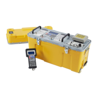
Explains how the EPM works with the PC6-IDOS calibrator.
Refers to the EPM user manual for safe connection and operation.
Illustrates a typical application setup with an EPM.
Steps for importing calibration procedures using SiCal PRO.
Procedure for logging calibration data points from a file.
Accessing logged calibration data and procedure details.
Steps for uploading completed calibration files back to SiCal PRO.
Illustration and specifications for panel mounting the device.
| Manufacturer | GE Druck |
|---|---|
| Category | Test Equipment |
| Communication Interface | RS232 |
| Pressure Range | Depends on IDOS module |
| Operating Temperature | 50°C |