Do you have a question about the GE Druck ADTS 405 and is the answer not in the manual?
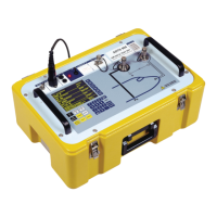
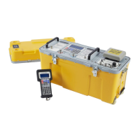
Provides an overview of the ADTS 405 and its versions.
Details the contents of the packaging for ADTS 405 and 405F units.
Outlines procedures for packing the unit for storage or repair.
Explains how to connect the unit to electrical power supplies safely.
Describes pneumatic connections for ADTS 405 rack and flight line units.
Covers safe positioning of ADTS 405F in hazardous areas.
Details pre-operation checks and connections for the ADTS 405.
Explains display options and unit conversions for data.
Provides a quick reference to key-pad functions and commands.
Guides new users through the initial power-up and system checks.
Describes the power-up sequence and initial system status checks.
Explains how to select parameters and set target values (aims).
Outlines the procedure for performing leak tests on the ADTS 405.
Explains how to change between pressure and aeronautical units.
Describes how the system checks data against set minimum and maximum limits.
Explains features for protecting aircraft systems against errors and leaks.
Details the SCPI IEEE 488 interface for remote control.
Explains the Altimeter Encoder Option for displaying encoded altimeter data.
Describes the ARINC 429 interface for transmitting aeronautical data.
Provides complete access to all secondary functions and unit selections.
Allows configuration of default aeronautical and pressure units.
Allows selection and programming of aircraft limit sets.
Configures dual channel operation and single channel testing modes.
Allows configuration of display types: single, dual, or triple.
Initiates a system self-test routine.
Allows changing the altitude correction value.
Enables or disables the auto zero function for airspeed accuracy.
Switches airspeed display between CAS and TAS.
Allows changing or disabling the Mach limit.
Allows setting Wait/Time values for the RATE TIMER function.
Selects automatic airspeed rate control ON or OFF.
Enables or disables the auto leak recovery facility.
Enables or disables the auto limit recovery facility.
Sets up the results file options for printing or saving.
Introduces operator maintenance tasks and their periodicity.
Details specific maintenance tasks (A-J) and their procedures.
Introduces the built-in self-test and diagnostic system.
Provides a procedure to check the functions and facilities of the ADTS 405.
Explains how self-test errors are displayed with error codes.
Details the procedure to vent pressure after an overpressure event.
Describes additional tests for pneumatic leaks or controller instability.
Explains how to test optional facilities like IEEE 488, Altimeter Encoder, ARINC 429.
Introduces fault diagnosis and lists error messages.
Lists warning messages, their causes, and recommended actions.
Introduces key functions and references to associated functions.
Describes the altitude and static pressure (Ps) display functions.
Explains airspeed (CAS/TAS) and dynamic pressure (Qc) display functions.
Describes Mach display and total pressure (Pt) display functions.
Explains the Engine Pressure Ratio (EPR) check and display.
Explains switching between Control and Leak Measure modes.
Describes ground pressure display and controlling pressures to atmospheric.
Details entering Remote Mode for external control of the unit.
Describes the facility to print displayed readings and user entries.
Explains using the Test Program Manager for aircraft and component testing.
Introduces SETUP and CONFIGuration modes for system customization.
Details how to change default settings and lock parameters.
Details physical, power, and performance specifications.
Covers stability, rate control, and control response characteristics.
Defines Zone 2 hazardous areas and safety precautions for ATEX equipment.
| Type | Air Data Test Set |
|---|---|
| Power Supply | 100 to 240 VAC, 50/60 Hz |
| Airspeed Range | 0 to 650 knots |
| Operating Temperature | 0 to 50°C |
| Communication | RS232, IEEE-488 |
| Housing | Rugged case |