Druck ADTS 405 Service Manual
K0171 Issue No. 1 Page 2-7
Pt Controller PCB
38. Remove the insulating sheet from the studs. Unscrew and remove the eight screws and
shakeproof washers securing the PSU to the right hand side of rear chassis.
39. Unscrew and remove the four screws securing the PSU to the front panel.
40. Remove the PSU and cover. It may help to carefully lever top cover upwards at a point near the
six pin connector.
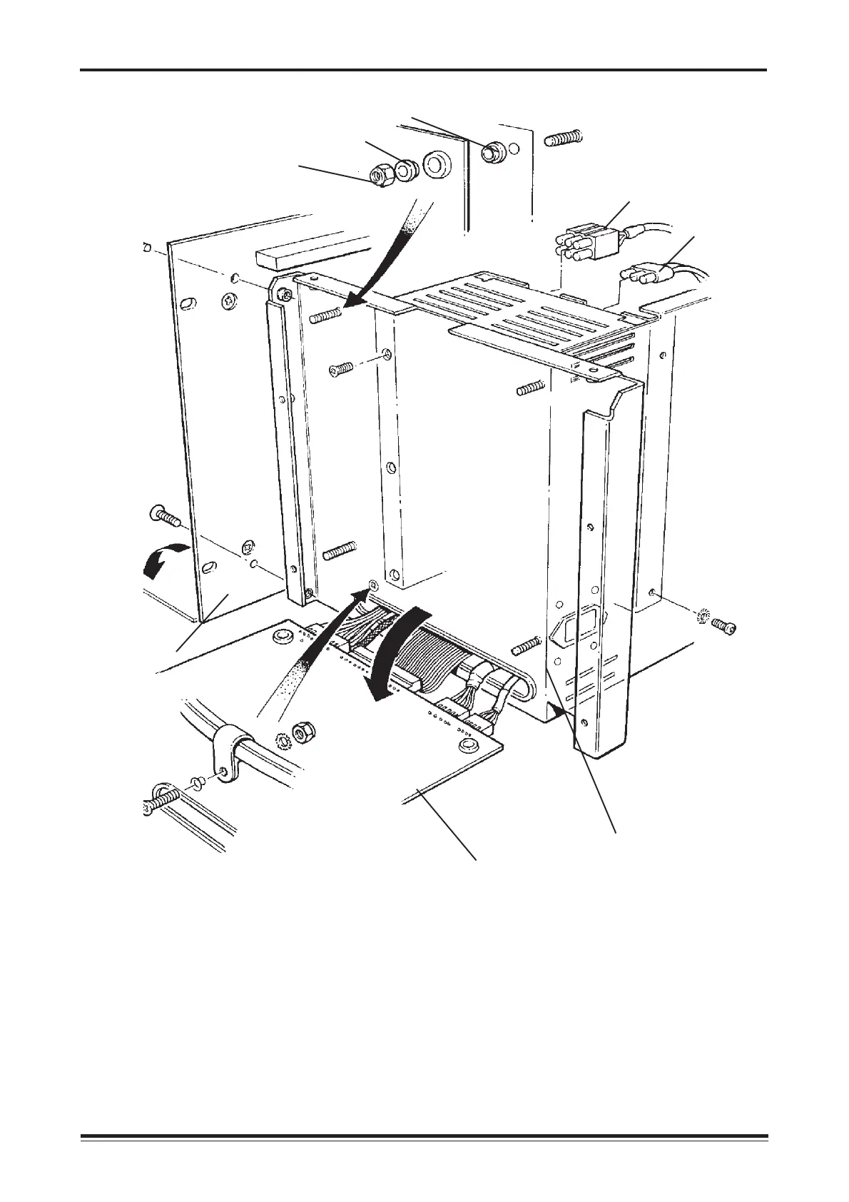
Figure 2.4 Power Supply Unit Installation
Side panel
Front panel
A.C. power
connector
D.C. power
connector
(option C)
Controller PCB
mounting detail Nylon spacer
Nylon spacer
Nyloc nut
 Loading...