GE Multilin G60 Generator Protection System 5-35
5 SETTINGS 5.2 PRODUCT SETUP
5
PRT2 IP ADDRESS = 10.1.2.2
PRT2 SUBNET IP MASK = 255.255.255.0
The behavior before release 7.10 was as follows. When sending packets to EnerVista, the UR noticed that the destination
was not on a connected network and it tried to find a route to destination. Since the default route was the only route it knew,
it used it. Yet EnerVista was on a private network, which was not reachable through Router 1. Hence a destination unreach-
able message was received from the router.
The configuration starting release 7.10 is as follows:
• PRT1 IP ADDRESS = 10.1.1.2
PRT1 SUBNET IP MASK = 255.255.255.0
PRT2 IP ADDRESS = 10.1.2.2
PRT2 SUBNET IP MASK = 255.255.255.0
IPV4 DEFAULT ROUTE: GATEWAY ADDRESS = 10.1.1.1
STATIC NETWORK ROUTE 1: RT1 DESTINATION = 10.1.3.0/24; RT1 NET MASK = 255.255.255.0; and RT1 GATE-
WAY = 10.1.2.1
The behavior since release 7.10 is as follows. There is one added static network route to the destination 10.1.3.0/24, where
a computer running EnerVista is located. This static route uses a different gateway (10.1.2.1) than the default route. This
gateway is the address of Router 2, which has knowledge about 10.1.3.0 and is able to route packets coming from UR and
destined to EnerVista.
SHOW ROUTES AND ARP TABLES
This feature is available on the Web interface, where the main menu contains an additional Communications menu and two
submenus:
• Routing Table
•ARP Table
The tables outline the information displayed when the two submenus are selected.
h) MODBUS PROTOCOL
PATH: SETTINGS PRODUCT SETUP COMMUNICATIONS MODBUS PROTOCOL
The serial communication ports utilize the Modbus protocol, unless the port is configured for DNP or IEC 60870-5-104
operation. This allows the EnerVista UR Setup software to be used on the port. The UR operates as a Modbus slave device
only.
Table 5–3: ROUTING TABLE INFORMATION
FIELD DESCRIPTION
Destination The IP address of the remote network to which this route points
Mask The network mask for the destination
Gateway The IP address of the next router to the remote network
Interface Interface through which the specified network can be reached
Table 5–4: IP ARP INFORMATION
FIELD DESCRIPTION
IP Address The network address that corresponds to Hardware Address
Age (min) Age, in minutes, of the cache entry. A hyphen (-) means the address is local.
Hardware Address LAN hardware address, a MAC address that corresponds to network address
Type Dynamic or Static
Interface Interface to which this address mapping has been assigned
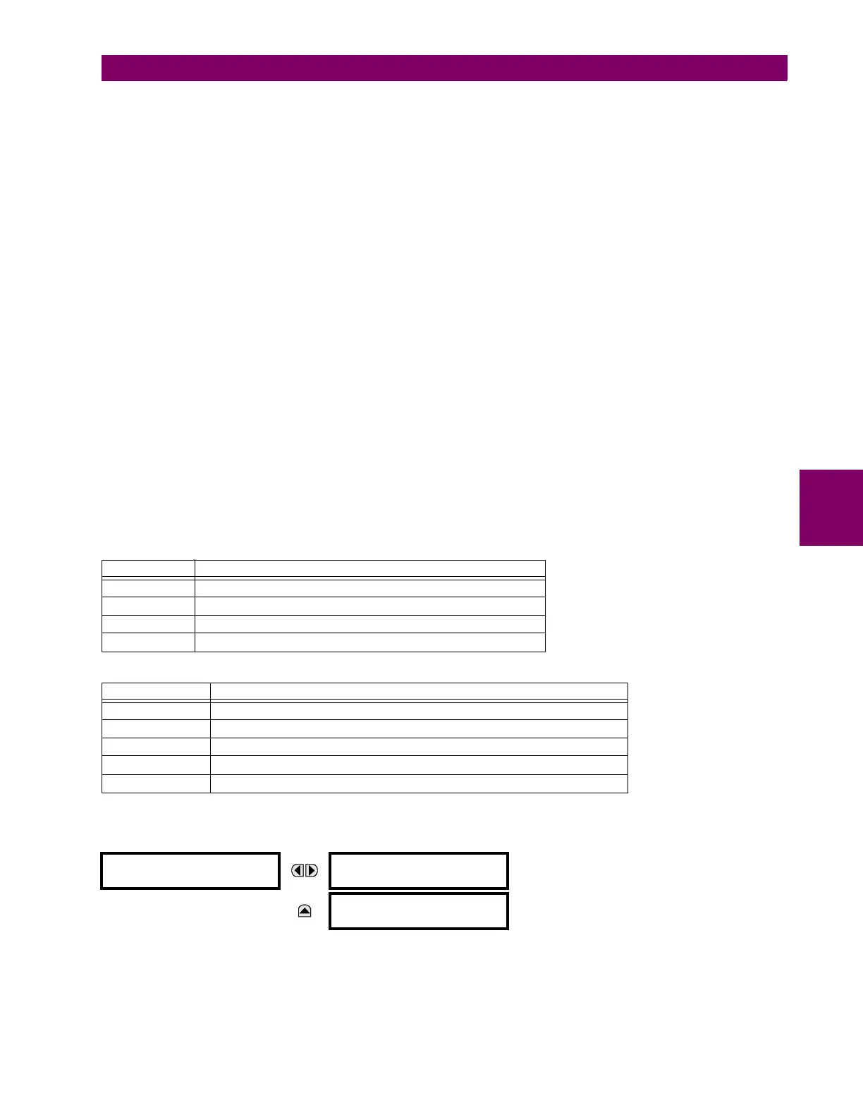
MODBUS PROTOCOL
MODBUS SLAVE
ADDRESS: 254
Range: 0 to 254 in steps of 1
MESSAGE
MODBUS TCP PORT
NUMBER: 502
Range: 0 to 65535 in steps of 1

 Loading...


