5-36 G60 Generator Protection System GE Multilin
5.2 PRODUCT SETUP 5 SETTINGS
5
When using Modbus protocol on the RS232 port, the G60 responds regardless of the MODBUS SLAVE ADDRESS pro-
grammed. For the RS485 port, each device on the serial bus must have a unique slave address from 1 to 254. Address 0
and addresses from 248 and up are reserved by the Modbus protocol specification, and so their use here is not recom-
mended. Address 0 is the broadcast address that all Modbus slave devices listen to. When
MODBUS SLAVE ADDRESS is set
to 0, the UR accepts broadcast messages, but in compliance with protocol specifications for broadcast messages, never
replies. Addresses do not have to be sequential, but no two devices can have the same address or conflicts resulting in
errors occur. Generally, each device added to the link should use the next higher address starting at 1. When using Modbus
TCP/IP, the client must use the programmed
MODBUS SLAVE ADDRESS value in the Unit Identifier field. See Appendix B for
more information on the Modbus protocol.
Modbus over TCP/IP can also be used on any of the Ethernet ports. The listening TCP port 502 is reserved for Modbus
communications, and only in exceptional cases when
MODBUS TCP PORT NUMBER is set to any other port. The MODBUS TCP
PORT NUMBER setting sets the TCP port used by Modbus on Ethernet. A MODBUS TCP PORT NUMBER of 0 disables Modbus
over TCP/IP, meaning closes the Modbus TCP port. When it is set to 0, use the front panel or serial port to communicate
with the relay.
When a 0 value is involved in a change, the changes to the MODBUS TCP PORT NUMBER setting take effect when the
G60 is restarted.
Do not set more than one protocol to the same TCP/UDP port number, as this results in unreliable operation of
those protocols.
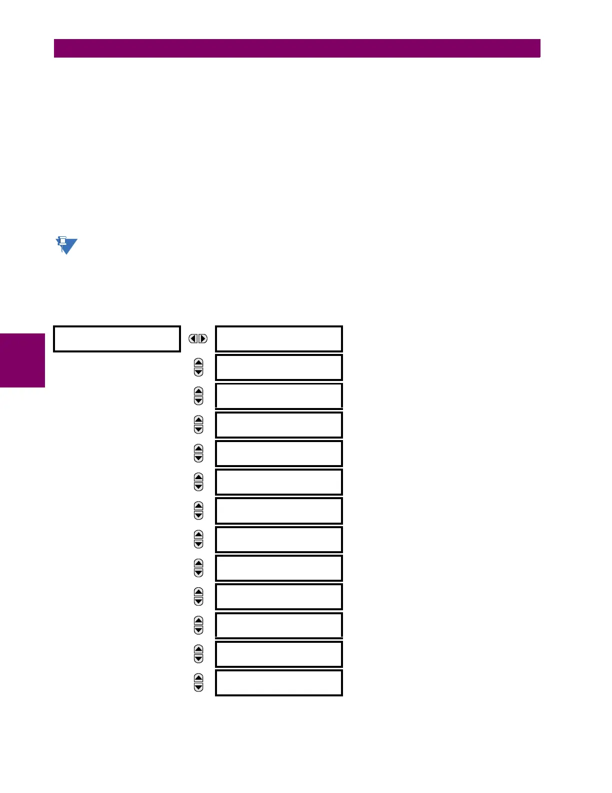
i) DNP PROTOCOL
PATH: SETTINGS PRODUCT SETUP COMMUNICATIONS DNP PROTOCOL
DNP PROTOCOL
DNP CHANNELS
Range: see sub-menu below
MESSAGE
DNP ADDRESS:
1
Range: 0 to 65519 in steps of 1
MESSAGE
DNP NETWORK
CLIENT ADDRESSES
Range: see sub-menu below
MESSAGE
DNP TCP/UDP PORT
NUMBER: 20000
Range: 0 to 65535 in steps of 1
MESSAGE
DNP UNSOL RESPONSE
FUNCTION: Disabled
Range: Enabled, Disabled
MESSAGE
DNP UNSOL RESPONSE
TIMEOUT: 5 s
Range: 0 to 60 s in steps of 1
MESSAGE
DNP UNSOL RESPONSE
MAX RETRIES: 10
Range: 1 to 255 in steps of 1
MESSAGE
DNP UNSOL RESPONSE
DEST ADDRESS: 1
Range: 0 to 65519 in steps of 1
MESSAGE
DNP CURRENT SCALE
FACTOR: 1
Range: 0.001, 0.01. 0.1, 1, 10, 100, 1000, 10000,
100000
MESSAGE
DNP VOLTAGE SCALE
FACTOR: 1
Range: 0.001, 0.01. 0.1, 1, 10, 100, 1000, 10000,
100000
MESSAGE
DNP POWER SCALE
FACTOR: 1
Range: 0.001, 0.01. 0.1, 1, 10, 100, 1000, 10000,
100000
MESSAGE
DNP ENERGY SCALE
FACTOR: 1
Range: 0.001, 0.01. 0.1, 1, 10, 100, 1000, 10000,
100000
MESSAGE
DNP PF SCALE
FACTOR: 1
Range: 0.001, 0.01. 0.1, 1, 10, 100, 1000, 10000,
100000
 Loading...


