GE Multilin G60 Generator Protection System B-15
APPENDIX B B.4 MEMORY MAPPING
B
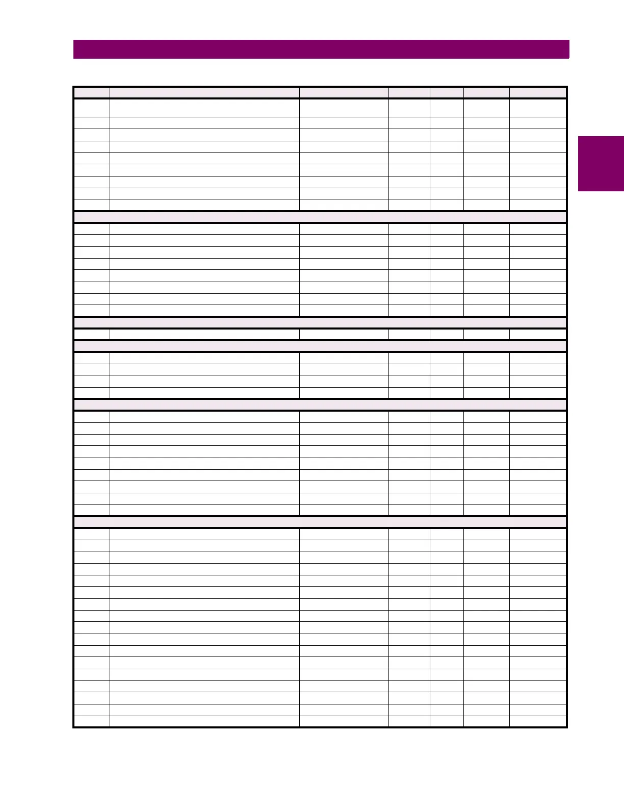
1C16 Source 1 Phase C Apparent Power -1000000000000 to
1000000000000
VA 0.001 F060 0
1C18 Source 1 Three Phase Power Factor -0.999 to 1 --- 0.001 F013 0
1C19 Source 1 Phase A Power Factor -0.999 to 1 --- 0.001 F013 0
1C1A Source 1 Phase B Power Factor -0.999 to 1 --- 0.001 F013 0
1C1B Source 1 Phase C Power Factor -0.999 to 1 --- 0.001 F013 0
1C1C Reserved (4 items) --- --- --- F001 0
1C20 ...Repeated for Source 2
1C40 ...Repeated for Source 3
1C60 ...Repeated for Source 4
Source Energy Metering (Read Only Non-Volatile) (4 modules)
1D00 Source 1 Positive Watthour 0 to 1000000000000 Wh 0.001 F060 0
1D02 Source 1 Negative Watthour 0 to 1000000000000 Wh 0.001 F060 0
1D04 Source 1 Positive Varhour 0 to 1000000000000 varh 0.001 F060 0
1D06 Source 1 Negative Varhour 0 to 1000000000000 varh 0.001 F060 0
1D08 Reserved (8 items) --- --- --- F001 0
1D10 ...Repeated for Source 2
1D20 ...Repeated for Source 3
1D30 ...Repeated for Source 4
Energy Commands (Read/Write Command)
1D60 Energy Clear Command 0 to 1 --- 1 F126 0 (No)
Source Frequency (Read Only) (4 modules)
1D80 Frequency for Source 1 2 to 90 Hz 0.001 F003 0
1D82 Frequency for Source 2 2 to 90 Hz 0.001 F003 0
1D84 Frequency for Source 3 2 to 90 Hz 0.001 F003 0
1D86 Frequency for Source 4 2 to 90 Hz 0.001 F003 0
Source Voltage THD and Harmonics (Read Only) (4 modules)
1F80 Source 1 Va THD 0 to 99.9 --- 0.1 F001 0
1F81 Source 1 Va Harmonics - 2nd to 25th (24 items) 0 to 99.9 --- 0.1 F001 0
1F99 Source 1 Vb THD 0 to 99.9 --- 0.1 F001 0
1F9A Source 1 Vb Harmonics - 2nd to 25th (24 items) 0 to 99.9 --- 0.1 F001 0
1FB2 Source 1 Vc THD 0 to 99.9 --- 0.1 F001 0
1FB3 Source 1 Vc Harmonics - 2nd to 25th (24 items) 0 to 99.9 --- 0.1 F001 0
1FCB ...Repeated for Source 2
2016 ...Repeated for Source 3
2061 ...Repeated for Source 4
Breaker Flashover (Read/Write Setting) (2 modules)
2196 Breaker Flashover 1 Function 0 to 1 --- 1 F102 0 (Disabled)
2197 Breaker Flashover 1 Side 1 Source 0 to 5 --- 1 F167 0 (SRC 1)
2198 Breaker Flashover 1 Side 2 Source 0 to 6 --- 1 F211 0 (None)
2199 Breaker Flashover 1 Status Closed A 0 to 4294967295 --- 1 F300 0
219B Breaker Flashover 1 Status Closed B 0 to 4294967295 --- 1 F300 0
219D Breaker Flashover 1 Status Closed C 0 to 4294967295 --- 1 F300 0
219F Breaker Flashover 1 Voltage Pickup Level 0 to 1.5 pu 0.001 F001 850
21A0 Breaker Flashover 1 Voltage Difference Pickup Level 0 to 100000 V 1 F060 1000
21A2 Breaker Flashover 1 Current Pickup Level 0 to 1.5 pu 0.001 F001 600
21A3 Breaker Flashover 1 Pickup Delay 0 to 65.535 s 0.001 F001 100
21A4 Breaker Flashover 1 Supervision Phase A 0 to 4294967295 --- 1 F300 0
21A6 Breaker Flashover 1 Supervision Phase B 0 to 4294967295 --- 1 F300 0
21A8 Breaker Flashover 1 Supervision Phase C 0 to 4294967295 --- 1 F300 0
21AA Breaker Flashover 1 Block 0 to 4294967295 --- 1 F300 0
21AC Breaker Flashover 1 Events 0 to 1 --- 1 F102 0 (Disabled)
21AD Breaker Flashover 1 Target 0 to 2 --- 1 F109 0 (Self-Reset)
21AE Reserved (4 items) --- --- --- F001 0
Table B–10: MODBUS MEMORY MAP (Sheet 7 of 68)
ADDR REGISTER NAME RANGE UNITS STEP FORMAT DEFAULT
 Loading...


