B-16 G60 Generator Protection System GE Multilin
B.4 MEMORY MAPPING APPENDIX B
B
21B2 ...Repeated for Breaker Flashover 2
Passwords Unauthorized Access (Read/Write Command)
2230 Reset Unauthorized Access 0 to 1 --- 1 F126 0 (No)
Synchrocheck Actual Values (Read Only) (4 modules)
2400 Synchrocheck 1 Delta Voltage -1000000000000 to
1000000000000
V1F060 0
2402 Synchrocheck 1 Delta Frequency 0 to 655.35 Hz 0.01 F001 0
2403 Synchrocheck 1 Delta Phase 0 to 359.9 degrees 0.1 F001 0
2404 ...Repeated for Synchrocheck 2
2408 ...Repeated for Synchrocheck 3
240C ...Repeated for Synchrocheck 4
Field Unit Raw Data Settings (Read/Write Setting)
2460 Field Raw Data Port 0 to 7 --- 1 F244 6 (H1a)
2461 Field Raw Data Freeze 0 to 1 --- 1 F102 0 (Disabled)
Phasor Measurement Unit Actual Values (Read Only)
2540 PMU 1 Phase A Voltage Magnitude 0 to 999999.999 V 0.001 F060 0
2542 PMU Unit 1 Phase A Voltage Angle -180 to 180 ° 0.1 F002 0
2543 PMU 1 Phase B Voltage Magnitude 0 to 999999.999 V 0.001 F060 0
2545 PMU 1 Phase B Voltage Angle -180 to 180 ° 0.1 F002 0
2546 PMU 1 Phase C Voltage Magnitude 0 to 999999.999 V 0.001 F060 0
2548 PMU 1 Phase C Voltage Angle -180 to 180 ° 0.1 F002 0
2549 PMU 1 Auxiliary Voltage Magnitude 0 to 999999.999 V 0.001 F060 0
254B PMU 1 Auxiliary Voltage Angle -180 to 180 ° 0.1 F002 0
254C PMU 1 Positive Sequence Voltage Magnitude 0 to 999999.999 V 0.001 F060 0
254E PMU 1 Positive Sequence Voltage Angle -180 to 180 ° 0.1 F002 0
254F PMU 1 Negative Sequence Voltage Magnitude 0 to 999999.999 V 0.001 F060 0
2551 PMU 1 Negative Sequence Voltage Angle -180 to 180 ° 0.1 F002 0
2552 PMU 1 Zero Sequence Voltage Magnitude 0 to 999999.999 V 0.001 F060 0
2554 PMU 1 Zero Sequence Voltage Angle -180 to 180 ° 0.1 F002 0
2555 PMU 1 Phase A Current Magnitude 0 to 999999.999 A 0.001 F060 0
2557 PMU 1 Phase A Current Angle -180 to 180 ° 0.1 F002 0
2558 PMU 1 Phase B Current Magnitude 0 to 999999.999 A 0.001 F060 0
255A PMU 1 Phase B Current Angle -180 to 180 ° 0.1 F002 0
255B PMU 1 Phase C Current Magnitude 0 to 999999.999 A 0.001 F060 0
255D PMU 1 Phase C Current Angle -180 to 180 ° 0.1 F002 0
255E PMU 1 Ground Current Magnitude 0 to 999999.999 A 0.001 F060 0
2560 PMU 1 Ground Current Angle -180 to 180 ° 0.1 F002 0
2561 PMU 1 Positive Sequence Current Magnitude 0 to 999999.999 A 0.001 F060 0
2563 PMU 1 Positive Sequence Current Angle -180 to 180 ° 0.1 F002 0
2564 PMU 1 Negative Sequence Current Magnitude 0 to 999999.999 A 0.001 F060 0
2566 PMU 1 Negative Sequence Current Angle -180 to 180 ° 0.1 F002 0
2567 PMU 1 Zero Sequence Current Magnitude 0 to 999999.999 A 0.001 F060 0
2569 PMU 1 Zero Sequence Current Angle -180 to 180 ° 0.1 F002 0
256A PMU 1 Frequency 2 to 90 Hz 0.001 F003 0
256C PMU 1 df/dt -327.67 to 327.67 Hz/s 0.01 F002 0
256D PMU 1 Configuration Change Counter 0 to 65535 --- 1 F001 0
256E Reserved (4 items) 0 to 1 --- 1 F001 0
Phasor Measurement Unit Integer (Read Only)
2608 PMU 1 SOC Timestamp 0 to 4294967295 seconds 1 F003 0
260A PMU 1 FRAMESEC Timestamp 0 to 4294967295 seconds 1 F003 0
260C PMU 1 STAT Flags 0 to 4294967295 --- 1 F003 0
Remote Double-Point Status Inputs (Read/Write Setting Registers) (5 modules)
2620 Remote Double-Point Status Input 1 Device 1 to 32 --- 1 F001 1
2621 Remote Double-Point Status Input 1 Item 0 to 64 --- 1 F606 0 (None)
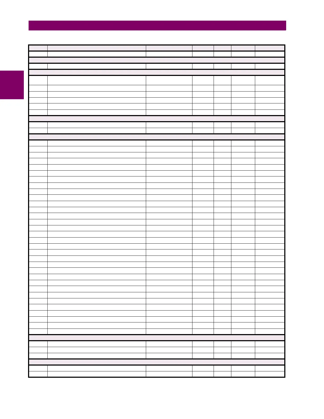
Table B–10: MODBUS MEMORY MAP (Sheet 8 of 68)
ADDR REGISTER NAME RANGE UNITS STEP FORMAT DEFAULT

 Loading...


