STEP 2 - Wire and configure GE Interlogix Open Collector Output
PRODUCT APPLICATION NOTEVideofied Upgrade - GE Interlogix
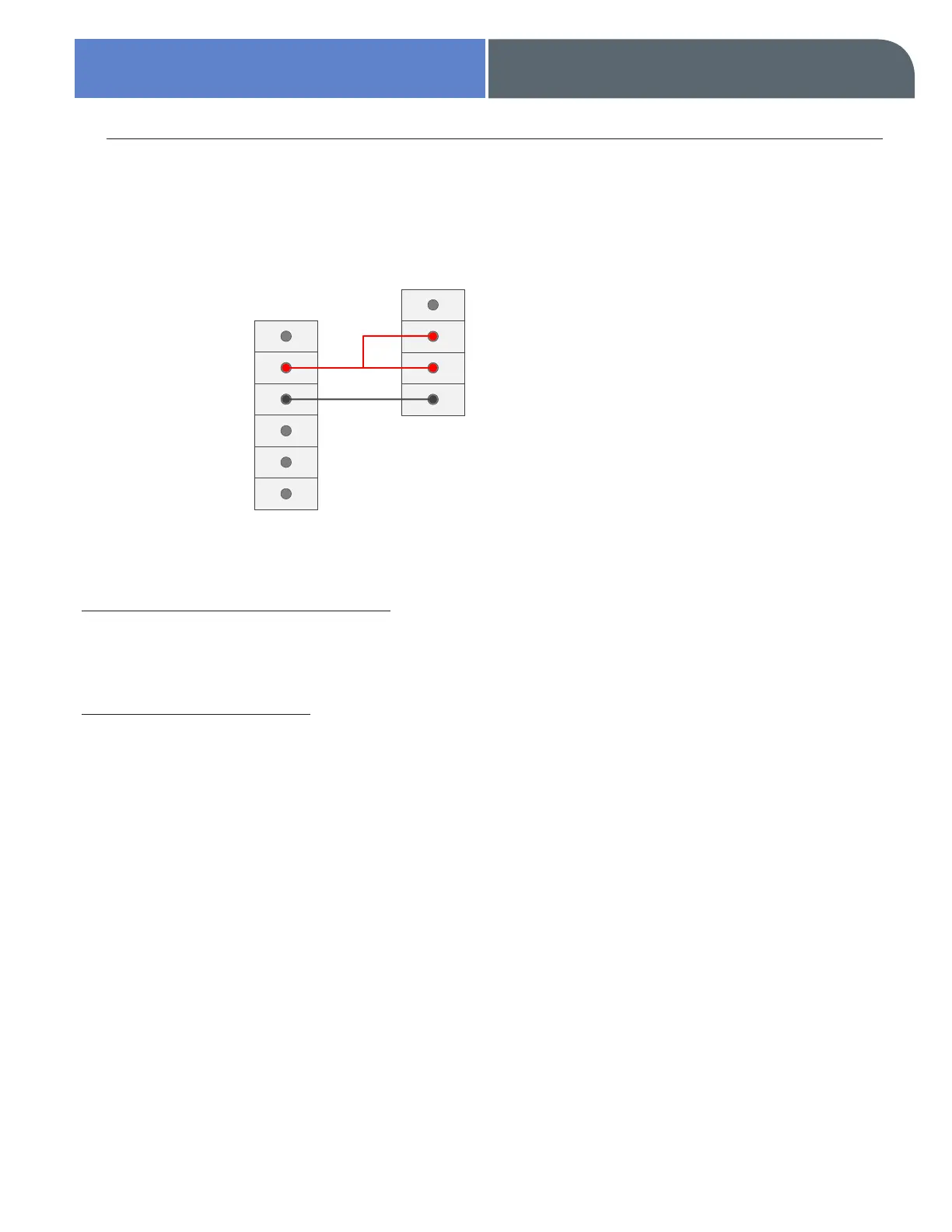
Connect SPDT Relay Module to the GE Interlogix Series Control Panel
Enter Installer / Programming Mode
Enter
*
8 then installer code
Configure Output Function: Videofied Upgrade to GE Interlogix series control panels requires
configuration of one output function for arming and disarming.
ARM FUNCTION
Enter Address of 0 (zero)
to configure output number 4 (or go to next unprogrammed output option)
Enter Location 50
Enter 21 in segment 1 (21 = armed state)
Enter 2 in Segment 2
> Refer to control panel manual for table of conditions
Press exit button twice to exit
GE Interlogix
Output 1
Output 2
Output 3
Output 4
Aux +
Aux -
4 Terminal SPDT Relay
NO
C
POS
+
NEG
-