PRODUCT APPLICATION NOTEVideofied Upgrade - GE Interlogix
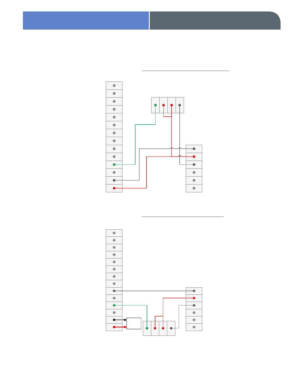
Wiring Diagram - GE Interlogix to Videofied Panel
Prog. Out. Com
Prog Output 2
Prog Output 1
Ref GND
Prog Input 3
Prog Input 2
Prog Input 1
Ref +
Ref GND
Arming Input 2
Arming Input 1
Ref +
PWR (-)
PWR (+)
Videofied Panel Terminal
Strip
GE Interlogix
Output 1
Output 2
Output 3
Output 4
Aux +
Aux -
4 Terminal SPDT Relay
NO C
POS
+
NEG
-
Prog. Out. Com
Prog Output 2
Prog Output 1
Ref GND
Prog Input 3
Prog Input 2
Prog Input 1
Ref +
Ref GND
Arming Input 2
Arming Input 1
Ref +
PWR (-)
PWR (+)
Videofied Panel Terminal
Strip
GE Interlogix
Output 1
Output 2
Output 3
Output 4
Aux +
Aux -
4 Terminal SPDT Relay
NO C
POS
+
NEG
-
12v
Power
Source
Note: Wiring will be different depending on if the Videofied control panel is being powered by a 12v Power
Supply or directly off of the AUX -/+ built into the GE Interlogix system. Both options are shown below
Videofied Powered by GE Interlogix
Videofied Powered by 12v Power