Do you have a question about the GE JB400DP1BB and is the answer not in the manual?
Information is for those with electrical/mechanical backgrounds; manufacturer not liable for misinterpretation.
Ensure grounding wires, screws, and clips are returned to original position after service.
GE service employees must use safety glasses with side shields, cut-resistant gloves, and steel toe shoes.
Safety glasses must meet ANSI Z87.1-2003 standards for protection.
GE covers defective parts and provides free labor and in-home service for one year.
Warranty excludes improper installation, misuse, accidents, cosmetic damage, and non-accessibility.
Explains brand, configuration, feature pack, model year, and color indicators in the model number.
The model and serial plate is located on the front frame behind the storage drawer.
The range must be secured with the supplied anti-tip bracket, ensuring screws enter wood or metal.
Fully open the door, then push the hinge locks down towards the frame to unlock them.
Seat the indentation of the hinge arm into the bottom edge of the hinge slot at the same angle as removal.
The door gasket is attached around the perimeter of the door using spring clips.
A gap must be left at the bottom of the gasket to provide necessary air flow for proper baking.
The door switch is a sensor input for door position, it does not control the oven light.
After lifting the cooktop, remove two 1/4" hex heads to release the switch assembly.
Open oven door, remove screws securing cooktop, and lift cooktop, using a prop if desired.
Details the 8-inch (2000W), 10-inch (3000W/1400W/1600W), and 6-inch (1500W) elements.
Mark numbered holes on the burner outer case, then lift the spring clip to disengage it.
Activates the Hot Cooktop Light when the surface unit is on and remains on until cooled below 150°F.
Detects high glass temperature (~1031°F), disconnects power, and resumes when temperature drops.
Disconnect two power plugs at the rear and remove the ground wire screw at the bottom.
Pull the cooktop towards the front to disengage hinge slots from frame pins after lifting.
Remove three 1½" hex heads at the top rear and two Phillips screws under the control panel.
Pull bottom out, lift panel up, and lay on cooking surface with a protective covering.
Sensor should read 1100Ω at room temp; test at ERC plug (pins 1&2) or sensor disconnect.
The oven sensor disconnect plug is visually identified on the back panel for service.
The T09 system comprises the control, key panel (single component), and oven sensor.
Pressing UP/DOWN arrows simultaneously blanks clock; pressing again restores it.
Hold Bake and Broil keys for 2 seconds to access SF for adjustments.
Press Bake key, display 'OO', use Up/Down to adjust temp +/-35 degrees in 1-degree steps.
Press Clock key in SF to cycle through ON (12hr), OFF (no shutdown), SAb modes.
Remove four 1/4" hex heads securing the ERC to the backsplash frame for removal.
The ERC identifies 2 white wires as the Sensor and Orange/Yellow wires as the Door Switch.
Depress each pad; expect audible tones and display changes indicating proper function.
Details voltages at ERC terminals L1-N, L1-L2, L1-BAKE, L1-BROIL in standby and active modes.
Press Kitchen Timer + Up/Down to display fault codes; press Kitchen Timer + Clock to clear them.
Press the Clear/Off pad to exit the fault code mode and return to normal operation.
Defines F2 (over-temp), F3 (open sensor), F4 (shorted sensor) and their correction steps.
Defines F7 (key matrix) and F8 (EEPROM) errors, typically requiring control replacement.
Oven temp must be <120°F and door closed; 'Hot' or 'dor' displayed if conditions unmet.
3-minute bake element operation followed by 27 minutes of cooling for a 30-minute total cycle.
Remove racks, pour 1 cup water into oven bottom, and close the door securely.
Press Steam Clean pad, then Start/On. The 30-minute cycle will begin counting down.
Oven beeps and Steam Clean light blinks on completion; press Clear/Off to end.
Use scrub brush/nylon pad for soil; avoid abrasive pads on glass. Dry with cloth or sponge.
Do not open door during cycle; if interrupted, cool oven before re-initiating.
Do not clean gasket. Use vinegar-soaked cloth for mineral deposits; wipe any water drips.
Check resistance at ERC or yellow/orange wire disconnect plug; it should be approximately 20Ω.
To replace element, remove the left side panel, starting with the hidden screw at the bottom front.
After lifting cooktop, remove two 1/4" hex heads and one Phillips screw from the top of the side panel.
Next, remove three 1/4" hex heads from the rear of the left side panel to allow access.
Grasp the panel and lift approximately one inch to release its tabs from the frame openings.
Carefully lift the insulation blanket and tuck it under the upper frame to create a clear work area.
Push down on the insulation retainer to clear it from the bake element compartment opening.
Remove orange/yellow leads from element terminals and two 1/4" hex heads securing the compartment cover.
Fold out or completely remove the compartment cover to gain access to the hidden bake element.
Slide the bake element out from its compartment to complete the removal process.
Upon re-insertion, the element's tabs must align with the slots or openings on the far side of the compartment.
Features a single 40W incandescent bulb with a clear glass cover held by a spring wire.
Explains operation of Bake/Time Bake, Broil, and Steam Clean cycles based on circuit diagrams.
Provides a schematic with wiring, component labels, and notes on element connections and relays.
A table lists wiring diagram items with their corresponding part numbers, descriptions, and quantities.
| Brand | GE |
|---|---|
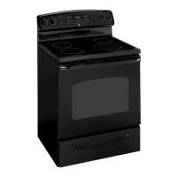
| Model | JB400DP1BB |
| Fuel Type | Electric |
| Number of Burners | 4 |
| Self-Cleaning | Yes |
| Color | Black |
| Type | Freestanding |
| Width | 29.875 inches |