GE Multilin L30 Line Current Differential System 3-41
3 HARDWARE 3.3 PILOT CHANNEL COMMUNICATIONS
3
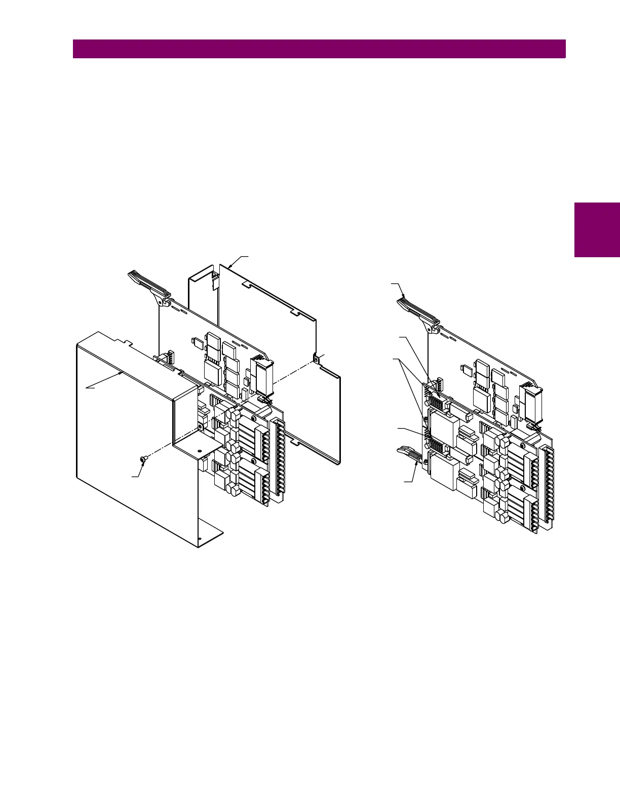
1. With power to the relay off, remove the IEEE C37.94 module (type 2I, 2J, 76 or 77 module) as follows. Record the orig-
inal location of the module to help ensure that the same or replacement module is inserted into the correct slot.
2. Simultaneously pull the ejector/inserter clips located at the top and at the bottom of each module in order to release the
module for removal.
3. Remove the module cover screw.
4. Remove the top cover by sliding it towards the rear and then lift it upwards.
5. Set the timing selection switches (channel 1, channel 2) to the desired timing modes (see description above).
6. Replace the top cover and the cover screw.
7. Re-insert the IEEE C37.94 module. Take care to ensure that the correct module type is inserted into the correct slot
position. The ejector/inserter clips located at the top and at the bottom of each module must be in the disengaged posi-
tion as the module is smoothly inserted into the slot. Once the clips have cleared the raised edge of the chassis,
engage the clips simultaneously. When the clips have locked into position, the module is fully inserted.
Figure 3–44: IEEE C37.94 TIMING SELECTION SWITCH SETTING
Cover screw
Top cover
Bottom cover
Ejector/inserter clip
Ejector/inserter clip
Timing selection
switches
Channel 1
Channel 2
FRONT
REAR
831774A3.CDR