3-42 L30 Line Current Differential System GE Multilin
3.3 PILOT CHANNEL COMMUNICATIONS 3 HARDWARE
3
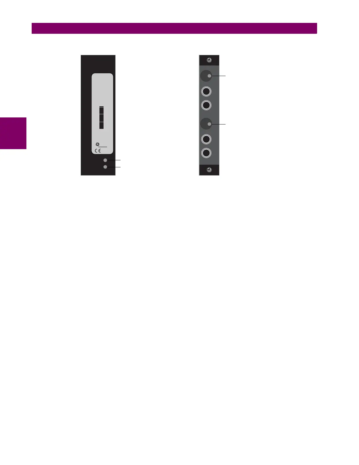
Modules shipped since January 2012 have status LEDs that indicate the status of the DIP switches, as shown in the follow-
ing figure.
Figure 3–45: STATUS LEDS
The clock configuration LED status is as follows:
• Flashing green — loop timing mode while receiving a valid data packet
• Flashing yellow — internal mode while receiving a valid data packet
• Solid red — (switch to) internal timing mode while not receiving a valid data packet
The link/activity LED status is as follows:
• Flashing green — FPGA is receiving a valid data packet
• Solid yellow — FPGA is receiving a "yellow bit" and remains yellow for each "yellow bit"
• Solid red — FPGA is not receiving a valid packet or the packet received is invalid
Tx1
Tx2
Rx1
Rx2
Tx1
Tx2
CH1 Link/Activity LED
CH2 Link/Activity LED
COMMS
2B
C37.94SM
1300nm single-mode
ELED
2 channel
Technical support:
Tel: (905)294-6222
Fax: (905)201-2098
(NORTH AMERICA)
1 800 547-8629
Made in Canada
GE Multilin
REV. D
CH1 Clock Configuration LED
CH2 Clock Configuration LED
FRONT VIEW REAR VIEW
842837A1.cdr