GE Multilin L30 Line Current Differential System 5-157
5 SETTINGS 5.5 FLEXLOGIC
5
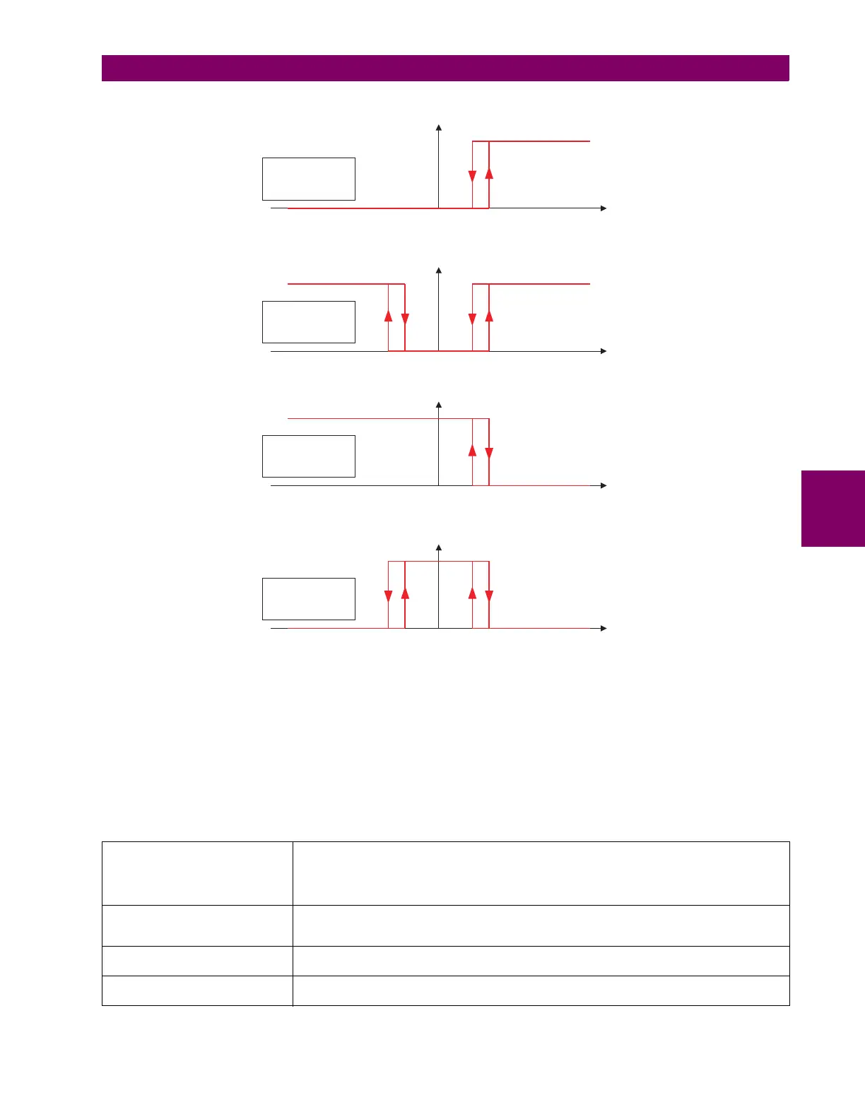
Figure 5–60: FLEXELEMENT INPUT MODE SETTING
The
FLEXELEMENT 1 PICKUP setting specifies the operating threshold for the effective operating signal of the element. If set
to “Over”, the element picks up when the operating signal exceeds the
FLEXELEMENT 1 PICKUP value. If set to “Under”, the
element picks up when the operating signal falls below the FLEXELEMENT 1 PICKUP value.
The FLEXELEMENT 1 HYSTERESIS setting controls the element dropout. It should be noticed that both the operating signal
and the pickup threshold can be negative facilitating applications such as reverse power alarm protection. The FlexElement
can be programmed to work with all analog actual values measured by the relay. The FLEXELEMENT 1 PICKUP setting is
entered in per-unit values using the following definitions of the base units:
Table 5–20: FLEXELEMENT BASE UNITS
87L SIGNALS
(Local IA Mag, IB, and IC)
(Diff Curr IA Mag, IB, and IC)
(Terminal 1 IA Mag, IB, and IC)
(Terminal 2 IA Mag, IB and IC)
I
BASE
= maximum primary RMS value of the +IN and –IN inputs
(CT primary for source currents, and 87L source primary current for line differential currents)
87L SIGNALS
(Op Square Curr IA, IB, and IC)
(Rest Square Curr IA, IB, and IC)
BASE = Squared CT secondary of the 87L source
BREAKER ACC ARCING AMPS
(Brk X Acc Arc Amp A, B, and C)
BASE = 2000 kA
2
× cycle
BREAKER ARCING AMPS
(Brk X Arc Amp A, B, and C)
BASE = 1 kA
2
× cycle
842706A2.CDR
FlexElement 1 OpSig
FLEXELEMENT 1 PKP
FLEXELEMENT
DIRECTION = Over;
FLEXELEMENT INPUT
MODE = Signed;
FlexElement 1 OpSig
FLEXELEMENT 1 PKP
FLEXELEMENT
DIRECTION = Over;
FLEXELEMENT INPUT
MODE = Absolute;
FlexElement 1 OpSig
FLEXELEMENT 1 PKP
FLEXELEMENT
DIRECTION = Under;
FLEXELEMENT INPUT
MODE = Signed;
FlexElement 1 OpSig
FLEXELEMENT 1 PKP
FLEXELEMENT
DIRECTION = Under;
FLEXELEMENT INPUT
MODE = Absolute;