B-44 L30 Line Current Differential System GE Multilin
B.4 MEMORY MAPPING APPENDIX B
B
7794 Thermal Protection 1 Events 0 to 1 --- 1 F102 0 (Disabled)
7795 Reserved (2 items) --- --- --- F001 0
7797 Repeated for Thermal Protection 2
Broken Conductor Detection (Read/Write Settings) (2 modules)
77AA Broken Conductor 1 Function 0 to 1 --- 1 F102 0 (Disabled)
77AB Broken Conductor 1 Source 0 to 5 --- 1 F167 0 (SRC 1)
77AC Broken Conductor 1 I2/I1 Ratio 20 to 100 % 0.1 F001 200
77AD Broken Conductor 1 I1 Minimum 0.05 to 1 pu 0.01 F001 10
77AE Broken Conductor 1 I1 Maximum 0.05 to 5 pu 0.01 F001 150
77AF Broken Conductor 1 Pickup Delay 0 to 65.535 s 0.001 F001 20000
77B0 Broken Conductor 1 Block 0 to 4294967295 --- 1 F300 0
77B2 Broken Conductor 1 Target 0 to 2 --- 1 F109 0 (Self-reset)
77B3 Broken Conductor 1 Events 0 to 1 --- 1 F102 0 (Disabled)
77B4 Reserved (2 items) --- --- --- F001 0
77B6 ...Repeated for Broken Conductor 2
Ohm Inputs (Read/Write Setting) (2 modules)
77F8 Ohm Inputs 1 Function 0 to 1 --- 1 F102 0 (Disabled)
77F9 Ohm Inputs 1 ID --- --- --- F205 "Ohm Ip 1 "
77FF Ohm Inputs 1 Reserved (9 items) 0 to 65535 --- 1 F001 0
7808 ...Repeated for Ohm Inputs 2
Phasor Measurement Unit Recorder Config Counter Command (Read/Write Command)
781A PMU 1 Recorder Clear Config Counter 0 to 1 --- 1 F126 0 (No)
Phasor Measurement Unit One-shot Command (Read/Write Setting)
788C PMU One-shot Function 0 to 1 --- 1 F102 0 (Disabled)
788D PMU One-shot Sequence Number 0 to 99 --- 1 F001 1
788E PMU One-shot Time 0 to 235959 --- 1 F050 0
Phasor Measurement Unit Recording Values (Read Only)
7890 PMU 1 Available Records 0 to 65535 --- 1 F001 0
7891 PMU 1 Second Per Record 0 to 6553.5 --- 0.1 F003 0
7893 PMU 1 Last Cleared Date 0 to 400000000 --- 1 F050 0
Phasor Measurement Unit Test Values (Read/Write Setting)
78AE PMU 1 Test Function 0 to 1 --- 1 F102 0 (Disabled)
78AF PMU 1 Phase A Voltage Test Magnitude 0 to 700 kV 0.01 F003 50000
78B1 PMU 1 Page A Voltage Test Angle -180 to 180 ° 0.05 F002 0
78B2 PMU 1 Phase B Voltage Test Magnitude 0 to 700 kV 0.01 F003 50000
78B4 PMU 1 Phase B Voltage Test Angle -180 to 180 ° 0.05 F002 -12000
78B5 PMU 1 Phase C Voltage Test Magnitude 0 to 700 kV 0.01 F003 50000
78B7 PMU 1 Phase C Voltage Test Angle -180 to 180 ° 0.05 F002 12000
78B8 PMU 1 Auxiliary Voltage Test Magnitude 0 to 700 kV 0.01 F003 50000
78BA PMU 1 Auxiliary Voltage Test Angle -180 to 180 ° 0.05 F002 0
78BB PMU 1 Phase A Current Test Magnitude 0 to 9.999 kA 0.001 F004 1000
78BD PMU 1 Phase A Current Test Angle -180 to 180 ° 0.05 F002 -1000
78BE PMU 1 Phase B Current Test Magnitude 0 to 9.999 kA 0.001 F004 1000
78C0 PMU 1 Phase B Current Test Angle -180 to 180 ° 0.05 F002 -13000
78C1 PMU 1 Phase C Current Test Magnitude 0 to 9.999 kA 0.001 F003 1000
78C3 PMU 1 Phase C Current Test Angle -180 to 180 ° 0.05 F002 11000
78C4 PMU 1 Ground Current Test Magnitude 0 to 9.999 kA 0.001 F004 0
78C6 PMU 1 Ground Current Test Angle -180 to 180 ° 0.05 F002 0
78C7 PMU 1 Test Frequency 20 to 70 Hz 0.001 F003 60000
78C9 PMU 1 Test df/dt -10 to 10 Hz/s 0.01 F002 0
Underfrequency (Read/Write Setting) (6 modules)
7A80 Underfrequency 1 Function 0 to 1 --- 1 F102 0 (Disabled)
7A81 Underfrequency 1 Block 0 to 4294967295 --- 1 F300 0
7A83 Underfrequency 1 Min Current 0.1 to 1.25 pu 0.01 F001 10
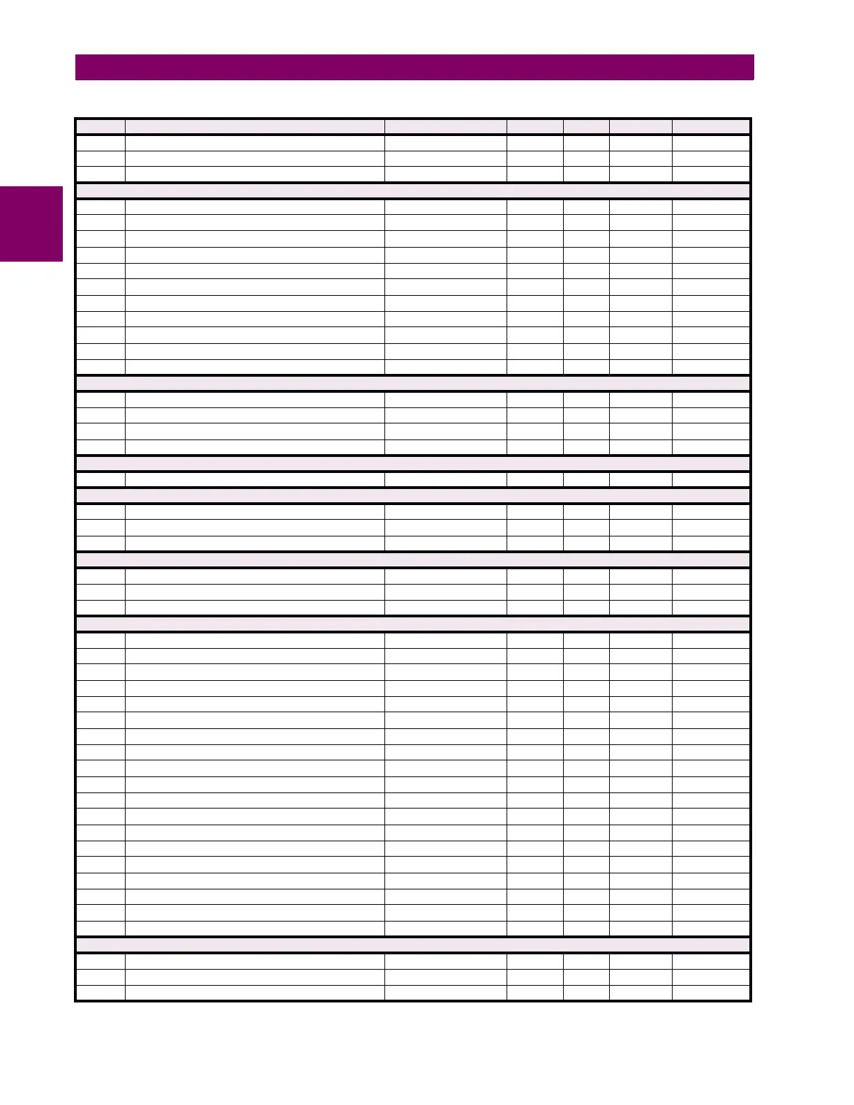
Table B–10: MODBUS MEMORY MAP (Sheet 36 of 63)
ADDR REGISTER NAME RANGE UNITS STEP FORMAT DEFAULT