GE LOGIQ V5/LOGIQ V3
D
IRECTION 5496012-100, REVISION 3 BASIC SERVICE MANUAL
Chapter 3 - System Setup 3 - 15
3-6-5Peripherals/Accessories Connector Panel (cont’d)
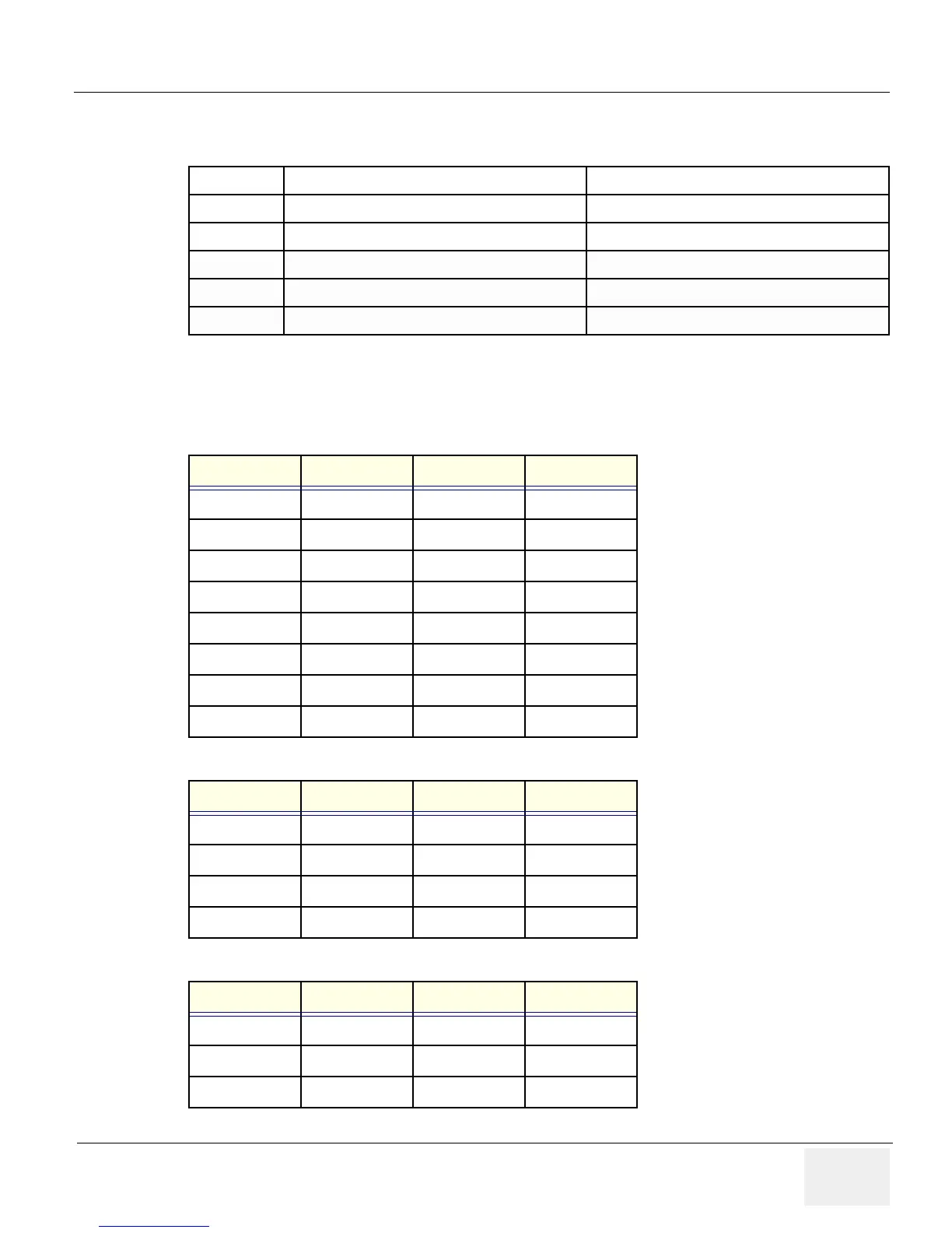
3-6-5-2 Pin assignment for each connector
Table 3-10 Peripheral/Accessory Connector Panel
1
HDMI port
HDMI out
2
Isolated Printer USB port
For AC Printer ONLY
3
USB Ports
USB Ports
4
Ethernet
LAN for InSite Connection (RJ45)
5
Circuit breaker
6.5A
6
AC Inlet
100-240V
Table 3-11 Pin Assignments of External VGA
Pin No. Signal Pin No. Signal
1RED9 NC
2 GREEN 10 NC
3BLUE11 NC
4NC12NC
5NC13HSY
6 GND 14 VSY
7 GND 15 NC
8GND
Table 3-12 Pin Assignments of USB
Pin No. Signal Pin No. Signal
1 +5 VDC 5 +5 VDC
2DATA6DATA
3DATA7DATA
4GND8GND
Table 3-13 Pin Assignments of Audio
Pin No. Signal Pin No. Signal
1GND4 NC
2L+5R+
3 Speaker L 6 Speaker R

 Loading...


