4
Insert the torque bar into the torque bar hole and secure it by
fitting the securing screw as shown in figure 4.
Fig. 4
Securing screw
Using a screwdriver, rotate the racking handle shutter drive,
clockwise (Fig. 5).
Note: If the circuit breaker is closed, this action will cause it to
trip.
Fig. 5
Insert the racking handle and rotate anti-clockwise until the
position indicator moves from CONNECTED through TEST to
DISCONNECTED.
Note:
• The circuit breaker cannot be operated:
(a) between positions
(b) in CONNECTED or TEST positions while the racking
handle is inserted.
• The circuit breaker can be operated while DISCONNECTED
with the handle in place.
• Removal of the handle automatically resets the racking handle
shutter.
From the DISCONNECTED position, continue turning the
racking handle anti-clockwise until reaching a positive stop.
Note: Ensure that the closing springs are fully discharged
(spring charge indicator should show ‘Discharged’) before
attempting to withdraw from the DISCONNECTED position.
Fig. 6
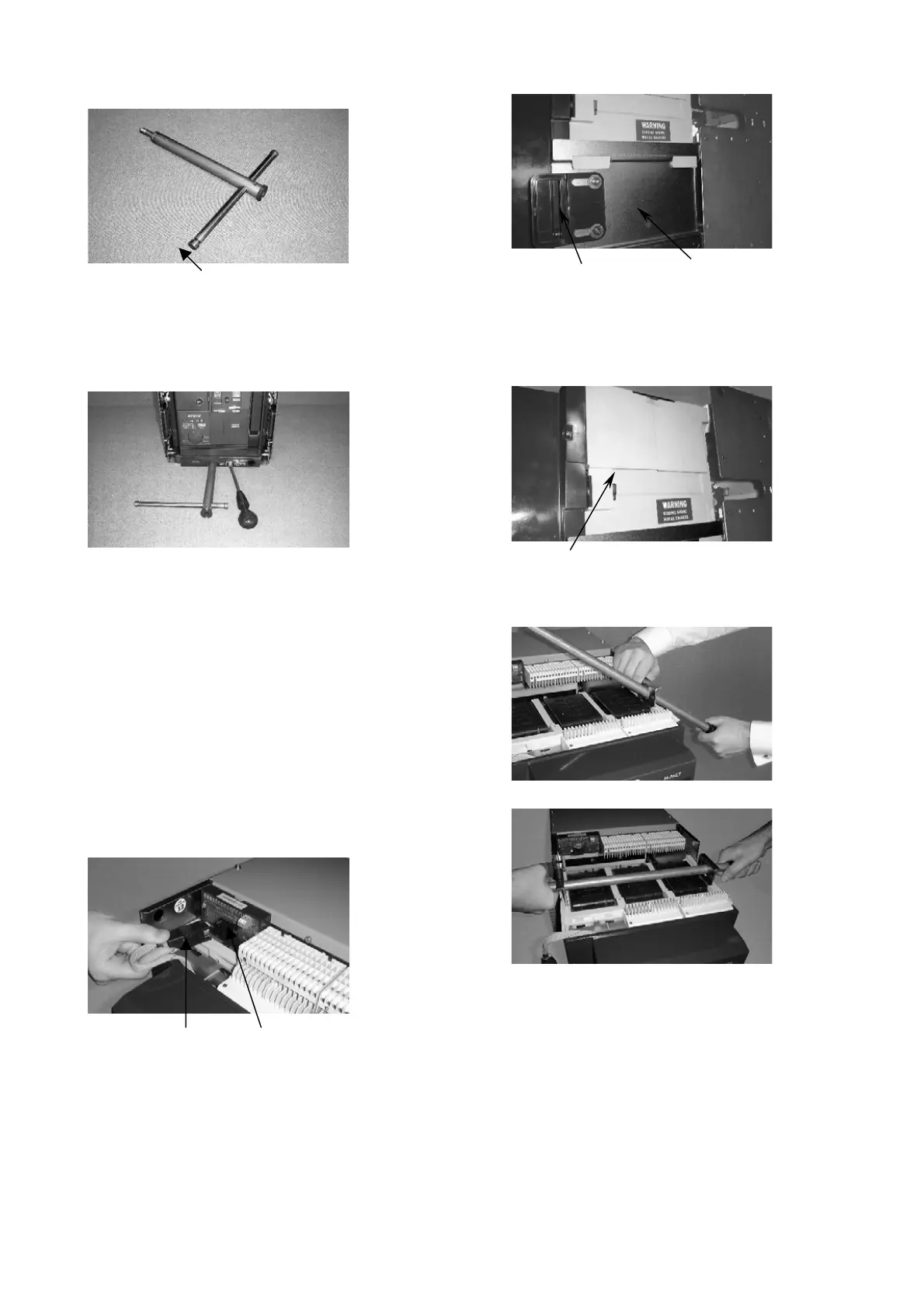
Plug connector PAMM unit
If a PAMM unit is fitted, remove plug connection. (Fig. 6).
Using the side rail handles, pull the circuit breaker out until
reaching a positive stop (Fig. 7).
The breaker is now in the maintenance position.
Fig. 7
Slide rail handle Slide rail
Removal of Circuit Breaker from
cassette
Lift the circuit breaker clear of the slide rails using the hand
grips on either side (Fig. 8).
Fig. 8
Hand grip
Lifting can be achieved utilising the retractable lifting eyes as
in Figs 9 and 10.
Fig. 9
Fig. 10