xii 2049809-001 Rev B © 2010 by General Electric Company. All rights reserved.
About this Manual
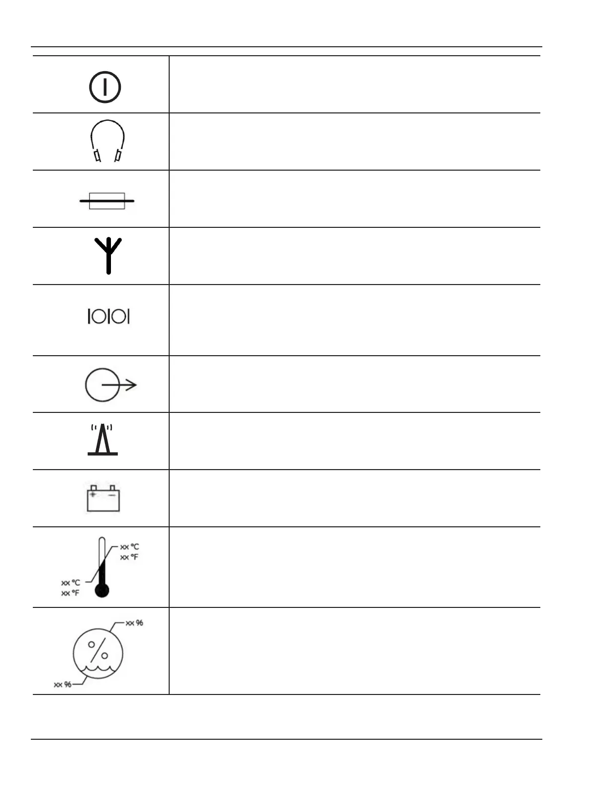
Transmitter Power ON / OFF (IEC 5010 symbol).
Audio head set (IEC 5077 symbol).
Fuse Symbol (IEC 5016 symbol).
Antenna Symbol (IEC 5039 symbol).
To identify a connector for a serial data connection.
Named as “ J2 “ on the Receiver back panel (IEC 5850 symbol).
To identify an output terminal when it is necessary to distinguish between inputs
and outputs.
Named as “J1 “on the Receiver back panel (IEC 5035 symbol).
Signal Strength Indicator on receiver front panel.
Battery Symbol on Receiver front panel (ISO 0247 symbol).
Temperature limitations in which the transport package has to be kept and
handled.
Humidity limitations in which the transport package has to be kept and handled.