12 3 SERIES RETROFIT – INSTRUCTION MANUAL
MIN AND MIN II RELAYS CHAPTER 1: OVERVIEW
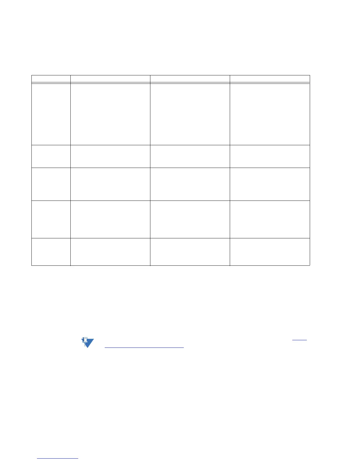
The following table describes MIN and MIN II options, and the equivalent 350 options and
order codes. In some cases the 350 options have changed from those available for MIN
and MIN II relays, so read the descriptions carefully.
Note
Order codes are subject to change without notice. See the GE Multilin website at: http://
www.gegridsolutions.com/multilin for up-to-date order codes.
Feature MIN order code options MIN II order code options 350 order code options
Function MIN-N-A0E000H00C
N: Ground directional relay
L
1
: Ground directional relay for
teleprotection schemes
MINII-N-A0EE00HI00
N: Ground directional relay
L: Ground directional relay for
teleprotection schemes
350EP0G0HE-E-N-R-SNNN
Current Protection E: Extended
configuration: User selectable 49,
50P(2), 50G/SG(2), 50N(2), 51P(1),
51G/SG(1), 51N(1)
Other Options R: Phase, Neutral, and
Ground Directional Overcurrent
Protection: 67P(1), 67N(1), 67G/SG(1),
32N(2), VTFF + Voltage, Power, and
Energy Metering, 60CTS
Curves MINN-A-0E000H00C
A: ANSI Curves
I: IEC Curves
MINIIN-A-0EE00HI00
A: ANSI Curves
I: IEC Curves
All 350 relays come with ANSI, IEC,
and IAC curves standard.
Ground CT
Range
MINNA0-E-000H00C
E: Ground CT In = 1 A or 5 A (10-
240% of CT rating)
S
2
: Isolated ground and Peterson
coil
MINIINA0-E-E00HI00
E: Ground CT In = 1 A or 5 A (10-
240% of CT rating)
S
2
: Isolated ground
3
and Peterson
coil
350EP0-G0-HEENRSNNN
G0: user selectable 1/5 A Ground
current input (0.02 - 20 × CT)
S0: user selectable 1/5 A Sensitive
Ground current input (0.002 - 3 × CT)
Power Supply MINNA0E000-H-00C
H:
110 - 250 VDC (Range: 88~300 VDC)
110 - 230 VAC (Range: 88~264 VAC)
F: 24 - 48 VDC (Range: 19~58 VDC)
MINIINA0EE00-HI-00
HI:
110 - 250 VDC (Range: 88~300 VDC)
110 - 230 VAC (Range: 88~264 VAC)
LO: 28 - 48 VDC (Range: 19~58 VDC)
350EP0G0-H-EENRSNNN
H: 110 - 250 VDC
110 - 230 VAC
L: 28 - 48 VDC
Environmental
Option
n/a MINIINA0EE00HI-00
00: None
0H: Conformal Coating
350EP0G0HEENRSNN-N
N: None
H: Harsh Environment Conformal
Coating
1. Option L is not available in the 3 Series.
2. Option S is not directly replaced in the 350 Feeder Protection System, however the Wattmetric Ground Fault element (32N) is a
substitute for MINII option S and detects feeder/line ground faults in solidly grounded, ungrounded, resistance grounded and res
-
onance grounded networks. It provides equivalent functionality to the Isolated Ground and Petersen Coil elements of the MIN II
relay.
Option S directional ground fault for Isolated or Peterson Coil grounded networks may also be replaced by P40 Agile P14D relays.
The P40 Agile P14D relay uses different algorithms to achieve more accurate High Impedance Fault detection; refer to the
P14D
Technical Manual, Chapter 6, Section 18.
3. For a detailed example of converting the MIN II Option "S" 67IG1 Isolated Ground function to the 350 32N function, see Converting
MIN II 67IG1 to 350 32N on page 29.

 Loading...


