CHAPTER 1: OVERVIEW MIW AND MIW II RELAYS
3 SERIES RETROFIT – INSTRUCTION MANUAL 13
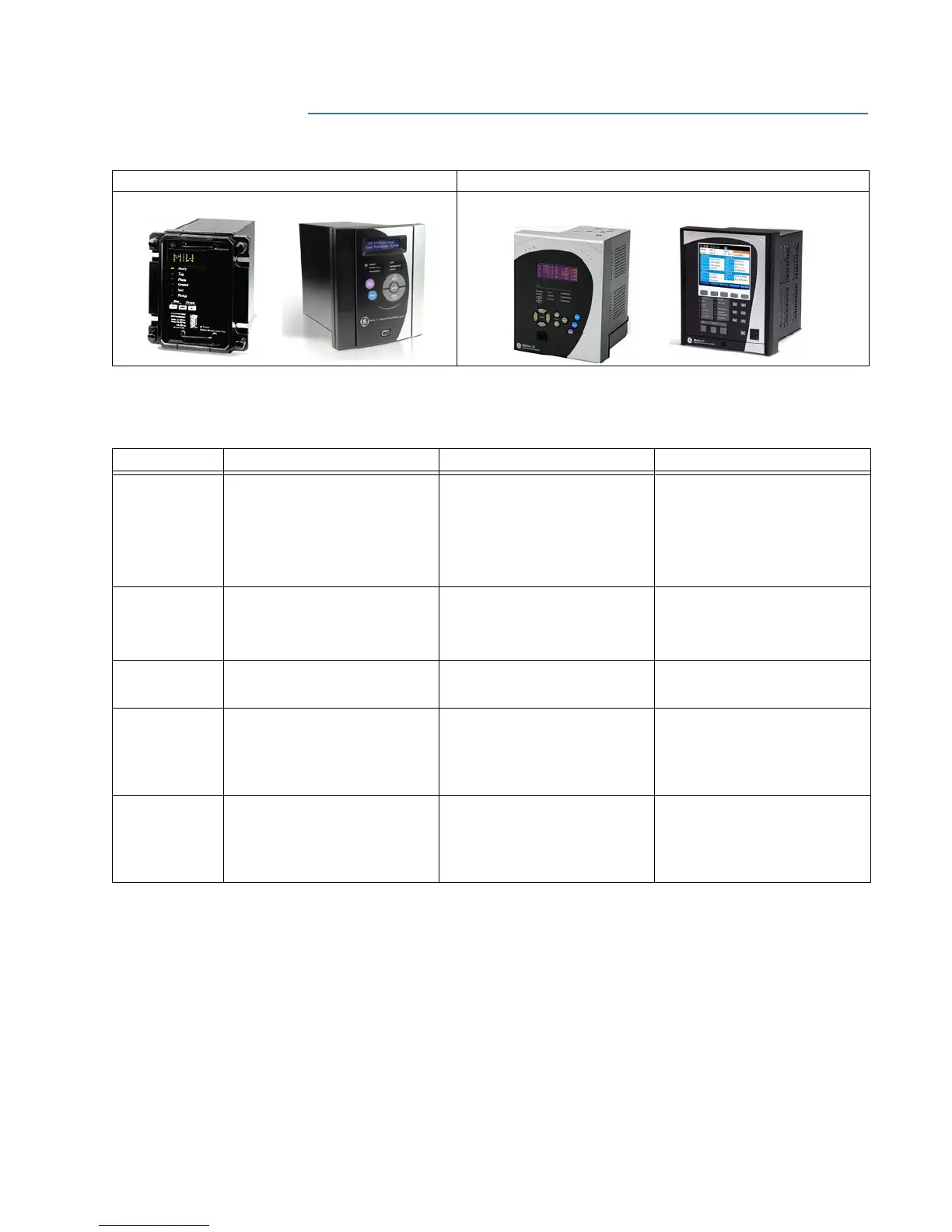
1.6 MIW and MIW II relays
Most MIW and MIW II features are available in 350 relays as described in the table below.
In some cases an 8 Series relay may be required to replace full functionality.
Installed Relay Retrofit Relay
MIW II Directional Power Protection System 350 Feeder Protection System or 889 Generator Protection System
Feature MIW MIW II
350
1
Protection &
Control
Directional Power: 32RP, 32FP, 32LF
40
60
Directional Power: 32(4)
40
60
Directional Power: 32(2)
Other Protection: 27P(2), 27X(1),
27P_1 (1), 59P(2), 59N(1), 59X(1),
59_2(1), 81O(2), 81U(2), 67P(1),
67N(1), 67G/SG(1), VTFF(1), 25(1),
60CTS
Metering &
Monitoring
Metering
Event Recording
Configurable IO and LEDs
Configurable Logic
Metering
Breaker Health
Event Recording
Programmable Logic Elements
...
Oscillography 8 samples/cycle
maximum length 24 cycles
8 samples/cycle
maximum length 24 cycles
up to 32 samples per cycle
(user-selectable)
maximum length 192 cycles
Communications Serial (RS232, RS485)
protocols: Modbus RTU
Serial (RS232, RS485)
protocols: Modbus RTU
USB
Serial (RS485) protocols: Modbus
RTU, DNP 3.0, IEC 60870-5-103
Ethernet protocols: Modbus TCP/IP,
DNP 3.0, IEC 60870-5-104, IEC 61850
GOOSE, IEC 61850, OPC-UA
Hardware 2 digital outputs
6 relay outputs
Configurable I/O
Configurable Logic
2 fixed LEDs
4 configurable LEDs
2 digital inputs
6 digital outputs
Configurable I/O
Configurable Logic
2 fixed LEDs
4 configurable LEDs
10 inputs
7 outputs (2 Form A, 5 Form C)
Configurable I/O
Configurable Logic
10 LEDs (non-programmable LEDs)
12 LEDs (programmable LEDs)
1. For additional features, refer to the 350 Instruction Manual.

 Loading...


