CHAPTER 3: INSTALLING THE 3 SERIES RELAY 3 SERIES DIMENSIONS AND MOUNTING
3 SERIES RETROFIT – INSTRUCTION MANUAL 35
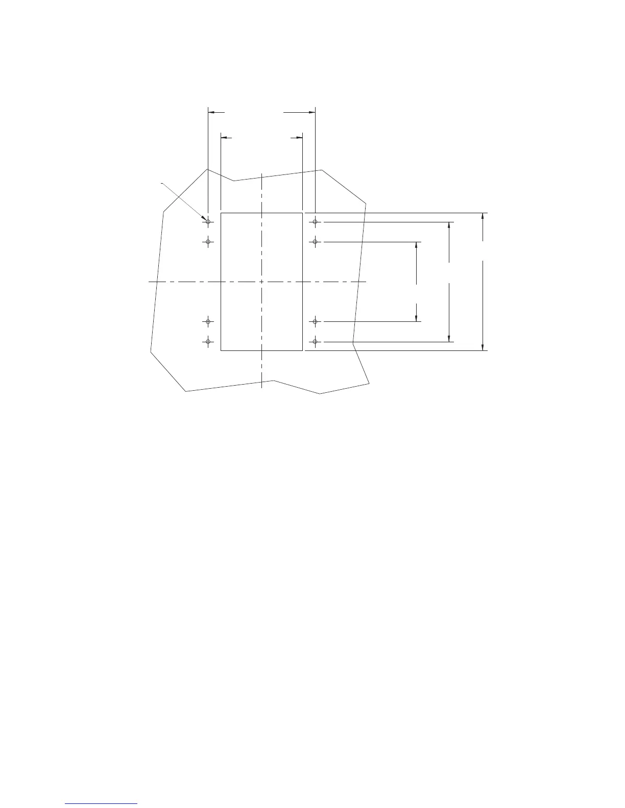
Figure 3-2: 3 Series panel cutout
The panel cutout used to mount the 3 Series relays is the same for the 350, 345, and 339
models. Eight screws are used to mount the relay from the back of the cutout panel.
Depth reducing collars are available in two widths as accessories:
• 18L0-0076 3 Series depth reducing collar - 1.375” (34.92 mm)
• 18L0-0075 3 Series depth reducing collar - 3.00” (76.20 mm)
Straight terminal block connectors are available for the non-drawout (NDO) 3 Series relays,
providing screws parallel to the wires for easier access when space is limited.
• 3S-NDO-STCONKIT 3 Series NDO straight terminal block kit
5.350” 0.010”
(135.9 mm 0.25mm)
±
±
4.100” 0.010”
(104.1 mm 0.25 mm)
±
±
0.200”
(5.1 mm)
Φ
6.900” 0.010”
(175.3 mm 0.25 mm)
±
±
6.000” 0.010”
(152.4 mm 0.25 mm)
±
±
4.000” 0.010”
(101.6 mm 0.25 mm)
±
±
C
L
C
L

 Loading...


