60 3 SERIES RETROFIT – INSTRUCTION MANUAL
MIF II/MIV II TO 350 RETROFIT WIRING CHAPTER 4: ELECTRICAL INSTALLATION
Power Supply Ground SCREW SCREW PS GND and
SCREW
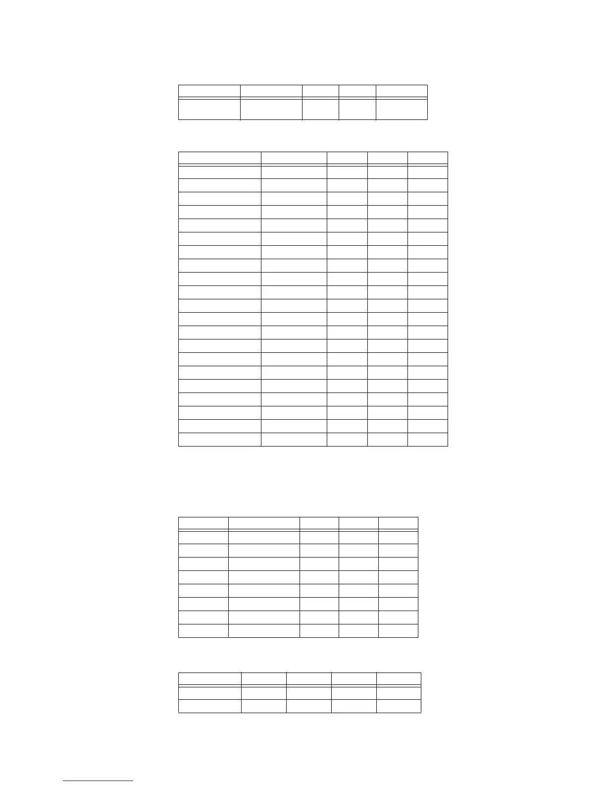
Table 4–14: I/O Contact Outputs
Type Function MIF II MIV II 350
Contact Output TRIP N/O A5 A5 A1
Contact Output TRIP COM A6 A6 A2
Contact Output TRIP OPTV NA NA A3
Contact Output CLOSE N/O NA NA A4
Contact Output CLOSE COM NA NA A5
Contact Output CLOSE OPTV NA NA A6
Contact Output AUX 3 N/C B7
1
1. By default the MIF II and MIV II relays are in the NO (Normally Open)
position. For the NC (Normally Closed) position, the output can be
modified by changing the jumper position on the hardware.
B7
*
A7
Contact Output AUX 3 COM A7 A7 A8
Contact Output AUX 3 N/O B7 B7 A9
Contact Output AUX 4 N/C B8
*
B8
*
A10
Contact Output AUX 4 COM A7 A7 A11
Contact Output AUX 4 N/O B8 B8 A12
Contact Output AUX 5 N/C B9
*
B9
*
A13
Contact Output AUX 5 COM A7 A7 A14
Contact Output AUX 5 N/O B9 B9 A15
Contact Output AUX 6 N/C B10
*
B10
*
A16
Contact Output AUX 6 COM A7 A7 A17
Contact Output AUX 6 N/O B10 B10 A18
Contact Output CRIT FAIL N/C B6 B6 A19
Contact Output CRIT FAIL COM A7 A7 A20
Contact Output CRIT FAIL N/O B5 B5 A21
Table 4–15: VT connections
Type Function MIF II MIV II 350
Voltages Va polarity NA B1 E9
Voltages Va non-polarity NA B2 D9
Voltages Vb polarity NA B3 E10
Voltages Vb non-polarity NA B4 D10
Voltages Vc polarity NA A3 E11
Voltages Vc non-polarity NA A4 D11
Voltages Vaux polarity NA NA E12
Voltages Vaux non-polarity NA NA D12
Table 4–16: I/O Contact Inputs
Type Function MIF II MIV II 350
Contact Input In1 A8 A8 B1
Contact Input In2 A9 A9 B2
Table 4–13: Control Power and Grounding connection
Type Function MIF II MIV II 350

 Loading...


