GEK-113000T F650 Digital Bay Controller 6-21
6 COMMISSIONING 6.14 OVERVOLTAGE ELEMENTS (59P, 59X, 59NH, 59NL, 47)
6
6.14.4 47 ELEMENT - NEG SEQ OV
Set the relay as follows:
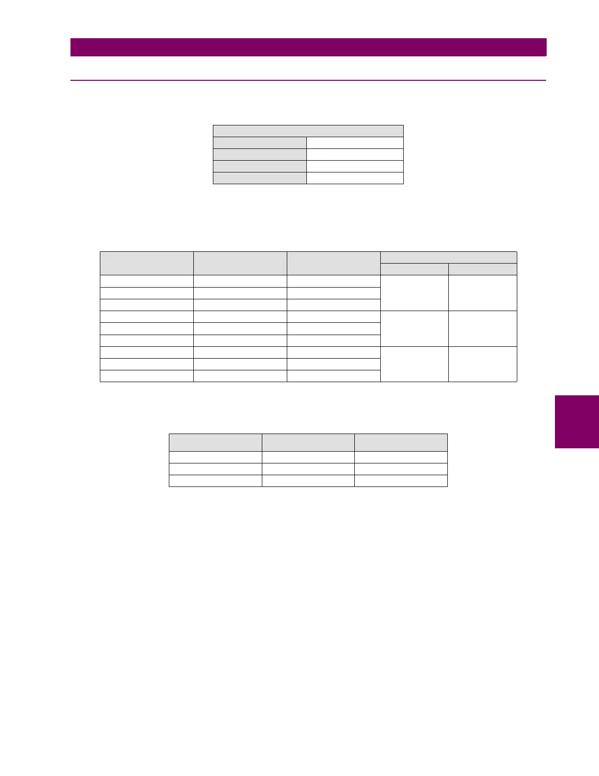
Apply voltage as indicated on the table under the overvoltage setting level and verify that the relay does not trip.
Verify that the relay trips for the set voltage (with an admissible error of 5%).
NOTE: All angles mentioned on the tables are delay angles, where a balanced ABC system would be composed by:
NEG SEQ OV (47)
Function ENABLED
Pickup Level 50 V
Trip Delay 2.00
Reset Delay 0.00
CHANNEL APPLIED VOLTAGE (V) ANGLE TRIPPING TIME (S)
EXPECTED ADMISSIBLE
VI 65 0º NO TRIP NA
VII 65 120º
VIII 65 240º
VI 55 0º 2 [1.9–2.1]
VII 55 240º
VIII 55 120º
VI 45 0º NO TRIP NA
VII 45 240º
VIII 45 120º
CHANNEL APPLIED VOLTAGE (V) ANGLE
VI 65 0º
VII 65 120º
VIII 65 240º

 Loading...


