GEK-113000T F650 Digital Bay Controller 3-19
3 HUMAN INTERFACES. SETTINGS & ACTUAL VALUES 3.1 ENERVISTA 650 SETUP SOFTWARE INTERFACE
3
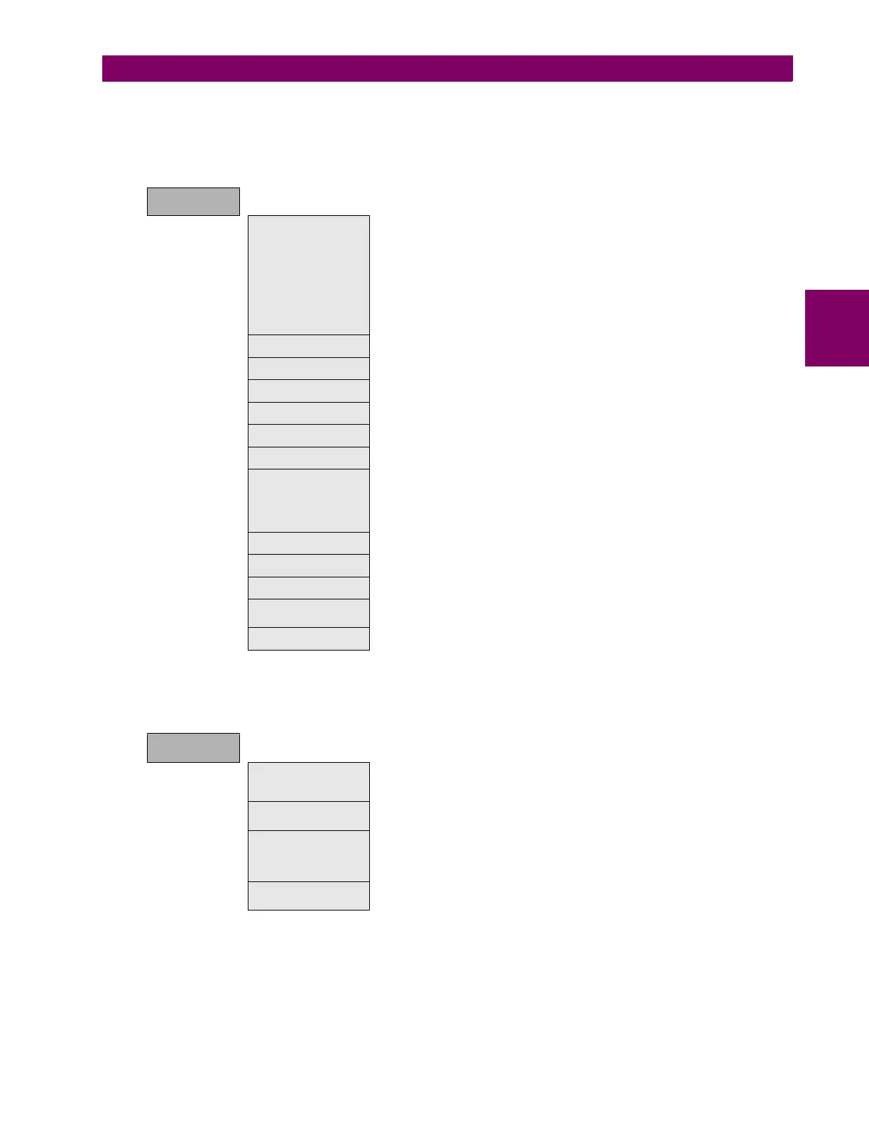
3.1.8.4 CONTROL ELEMENTS
This option shows all the control elements available in the relay as shown in Table 3–11:. Some of the elements are
grouped ones such as underfrequency, overfrequency and broken conductor.
Table 3–11: GENERAL OVERVIEW OF CONTROL ELEMENTS MENU:
3.1.8.5 INPUT/OUTPUTS
Section that contains the settings for all input and output boards and the Force Outputs and Virtual inputs activation tools.
Table 3–12: GENERAL OVERVIEW OF “INPUTS/OUTPUTS” SETTINGS MENU.
Options enabled only in On-line mode are marked as (*). Options enabled only in Off-line mode are marked as (**)
This section shows the settings related to inputs and outputs for the different boards available in F650 (F, G, H, J).
CONTROL
ELEMENTS
Setting Group
F650 units incorporate a flexible grouping capability for protection units.
This means that protection units can be used in either single setting
group (default mode-all units can operate simultaneously) or three
setting groups (in this mode, protection units are grouped in three
independent tables, with only one of them active at a given time).
Protection element grouping involves only Protection elements together
with broken conductor detection and over and under frequency, which
are usually considered as control elements. The rest of control elements
such as recloser, fuse failure, breaker failure, synchronism, and breaker
settings are not involved in the tabled groups concept.
Underfrequency Underfrequency unit (81U). Grouped element
Overfrequency Overfrequency unit (81O). Grouped element
Synchrocheck Synchronism check unit (25). Not grouped, a single unit provided
Autoreclose Recloser (79). Not grouped, a single unit provided
Breaker Failure Breaker failure (50BF). Not grouped, a single unit provided.
VT Fuse Failure Fuse Failure (VTFF). Not grouped, a single unit provided.
Broken Conductor
Broken or fallen conductor detection function (I2/I1). Grouped element.
Ratio between the negative sequence current, I2, and the positive
sequence current I1. In normal and balanced load situations, this ratio is
zero, while in severe load fault conditions, an unbalance is produced and
this ratio is increased.
Locked Rotor Locked rotor detection function (48). Grouped element.
Pulse Counters Pulse counters function. 8 counters provided.
Analog Comparators Analog comparator function. 20 analog comparators provided.
Frequency rate of
change
Frequency rate of change function (81R).Grouped element.
Load Encroachment Load Encroachment function. Grouped element.
INPUTS/
OUTPUTS
Contact I/O
Inputs and outputs settings for all boards in F650. The I/O settings
configuration can only be performed through EnerVista 650 Setup, not
HMI available.
Force Outputs (*)
This menu allows activating each contact output in the relay, to facilitate
maintenance testing. On line mode only.
Virtual Inputs (*)
This menu allows operating virtual inputs. These variables are used as
inputs to logic schemes configured in the relay. Virtual inputs can be
operated in a latched mode (32 latched virtual inputs) or in Self-reset
mode (32 self reset virtual inputs).
Remote Comms.
This menu allows configuring remote inputs coming from other devices
through GSSE messages. Available for IEC61850 (6) models only.

 Loading...


