GEK-113000T F650 Digital Bay Controller 3-25
3 HUMAN INTERFACES. SETTINGS & ACTUAL VALUES 3.1 ENERVISTA 650 SETUP SOFTWARE INTERFACE
3
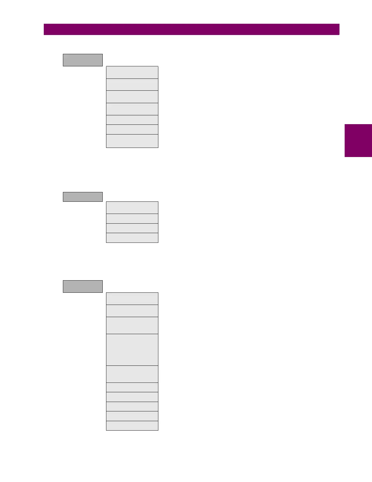
Table 3–19: ACTUAL VALUES RELATED TO RECORDING FUNCTIONS IN THE RECORDS STATUS MENU:
3.1.9.3 METERING
The Metering menu includes all the measurements available in the device. Primary and secondary values, and also the
data related to the recording functions in the relay.
Table 3–20: GENERAL OVERVIEW OF METERING MENU:
3.1.9.4 INPUTS/OUTPUTS
The Inputs/Outputs menu includes all the inputs and outputs signals available in the device. Contact and virtual type.
Table 3–21: GENERAL OVERVIEW OF INPUTS/OUTPUTS MENU:
RECORD
STATUS
Fault Reports This menu shows the fault report status signals, as fault report trigger,
fault date, fault type and location, besides the fault report number.
Control Events Status of the control events (if the signal configured to launch the control
event is active or not).
Oscillography Status of signals related to oscillography recording, such as status or
digital channels, oscillography trigger, number of records available, etc.
Data Logger Data logger information about oldest and newest sample time stamp,
and number of channels and days configured in data logger settings.
Demand Demand trigger and reset inputs status.
Energy Freeze, unfreeze and reset input signals for energy counters.
Breaker Maintenance All signals related to breaker maintenance, such as number of openings,
closings, (KI)
2
t counters, alarm signal for (KI)
2
t, etc.
METERING
Primary Values Primary values measurements for currents, voltages, power, energy and
demand
Secondary Values Secondary values measurements for currents, voltages and power.
Phasor Diagram Current, voltage and sequence components.
Frequency Line and Bus frequencies.
INPUTS/
OUTPUTS
Contact Inputs Status of digital inputs in the Relay for each board according to the relay
model.
Contact Output Status Status of digital outputs in the Relay for each board according to the relay
model.
Contact Outputs
Operates
Status (activated or not) of the variables used to operate a contact
output. To configure these signals go to “Setpoint>Relay
Configuration>Outputs” menu.
Contact Outputs
Resets
Status (activated or not) of the variables used to reset a contact output.
To configure these signals go to “Setpoint>Relay Configuration>Outputs”
menu. This output reset Command will only be effective if the “latch”
option has been Selected for the “Output Type” setting on the I/O board,
thus when the contact output has been configured to emulate function 86
(latching relay).
IO Board Status Status of I/O boards. This status provides if the hardware it is OK (boards
matching relay model, correctly inserted in their tracks, in good state and
communicating through the internal CAN Bus).
Virtual Inputs Status of Virtual inputs latched (32) and self-reset (32).
Virtual Outputs Status of virtual outputs (configured in PLC Editor). Up to 512.
Remote Outputs States of remote outputs for IEC61850 models.
Remote Inputs Status of remote device and remote inputs for IEC61850 models.
Analog Inputs (*) Measurements coming from analog inputs (DCMA)

 Loading...


