OEC 9800 Installation Procedure
11
TB1
200-250 VAC CORD ASM
BRN
BRN
CB1
BRN
WHT/BRN
BLU
10A
10A
BLU
1
BLU
3
5
GRN/YEL
RESET ONLY
1
5
3
9
6
8
E1
DS1
GREEN LAMP
AC POWER
20 FT/30 FT CORD
MOUNTING PLATE
BRN BRN
BRN
CB1 RESET ONLY
CB2 RESET ONLY
MOUNTING PLATE
GREEN LAMP
AC POWER
DS1
BLU
BLU
GRN/YEL
BLU
1
3
5
2
4
6
1
3
2
4
1
3
2
4
1
3
5
6
9
8
E1
20 FT CORD
TB1
100-127 VAC CORD ASM
20A
20A
10A
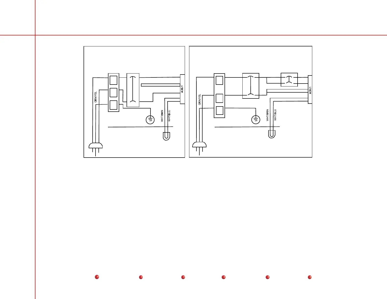
Figure 4 −
−−
− Power Cord Asm.
Note: The factory has attempted to provide the proper power cable plug assembly, but due to different international
requirements, the proper power plug assembly may not be furnished. If assistance is required, contact GE OEC Medical
Systems, Inc.
WARNING
Electrical circuits inside the equipment use voltages that are capable of causing serious injury
or death from electrical shock. Use appropriate precautions.

 Loading...


