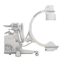
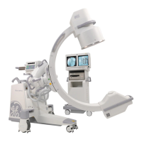
OEC 9800 Installation Procedure
13
found in the row described by voltage range 110.0 to 115.9. Connect the wires as described in that row.
For Example: If the voltage measured equals 224 VAC, use Table 2 (220 – 250 VAC). The correct voltage taps would be
found in the row described by voltage range 220.0 – 231.9 VAC. Connect the wires as described in that row.
3. Find the corresponding voltage range in the first column of the table and determine the voltage taps.
Table 1 (100 - 127 VAC )
If the AC line
voltage
determined in
ste
1 is
Connect
WHT/BLU
wire to
Primar
#1
Connect BRN
wire to Primary
#1 terminal…
Connect BLU
wire to
Primary #2
terminal…
Connect
WHT/BRN
wire to
Primar
#2
104.0 to 109.9 6 113 6 113
110.0 to 115.9 0 113 0 113
116.0 to 121.9 6 125 6 125
122.0 to 128.0 0 125 0 125
0 101 125 6 113
PRIMARY 1PRIMARY 2
6 113 0 101 125
WHT/BLU BRNBLU WHT/BRN
Figure 6 −
−−
− Isolation Transformer (T1) Tap Locations for 112 VAC

 Loading...


