P44x/EN CM/Hb
MiCOM P40 Agile P442, P444
(CM) 9-
The main groups of relay terminals are:
• Voltage transformer circuits.
• Current transformer circuits
• Auxiliary voltage supply.
• Field voltage output and opto-isolated control inputs.
• Relay contacts.
• RS485 communication port.
• Case earth.
The insulation resistance should be greater than 100 MΩ at 500 V.
On completion of the insulation resistance tests, ensure all external wiring is correctly
reconnected to the unit.
4.1.5 Watchdog Contacts
Using a continuity tester, check that the normally closed watchdog contacts are in the states
given in Table 2 for a de-energised relay.
Terminals
Contact State
Relay De-energised Relay Energised
J11-J12
N11-N12
(P442)
(P444)
Closed Open
J13-J14
N13-N14
(P442)
(P444)
Open Closed
Table 2 - Watchdog Contact Status
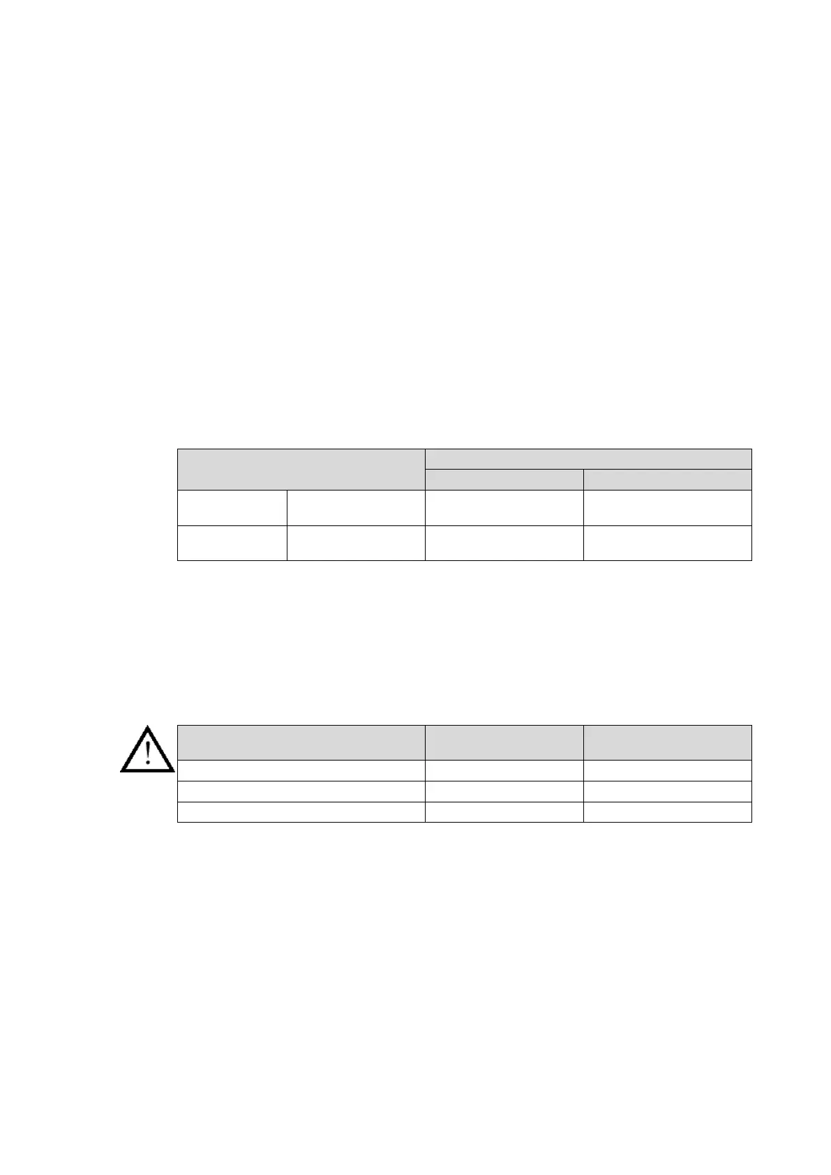
4.1.6 Auxiliary Supply
The relay can be operated from either a dc only or an ac/dc auxiliary supply depending on
the relay’s nominal supply rating. The incoming voltage must be within the operating range
specified in Table 3.
Without energising the relay, measure the auxiliary supply to ensure it is within the operating
range.
Nominal Supply Rating
DC Operating Range AC Operating Range
24/54 V [-] 19 – 65 V -
48/110 V [30/100 V] 37 – 150 V 24 – 110 V
110/250 V [100/240 V] 87 – 300 V 80 – 265 V
Table 3 - Operational Range of Auxiliary Supply
The relay can withstand an ac ripple of up to 12% of the upper rated voltage on the dc
auxiliary supply.
Do not energise the relay using the battery charger with the battery disconnected as
this can irreparably damage the relay’s power supply circuitry.
Energise the relay if the auxiliary supply is within the operating range. If an MMLG test block
is provided, it may be necessary to link across the front of the test plug to connect the
auxiliary supply to the relay.
4.2 With the Relay Energised
The following group of tests verify that the relay hardware and software is functioning
correctly and should be carried out with the auxiliary supply applied to the relay.
The current and voltage transformer connections must remain isolated from the relay for
these checks.