MiCOM P40 Agile P442, P444
(GS) 3-
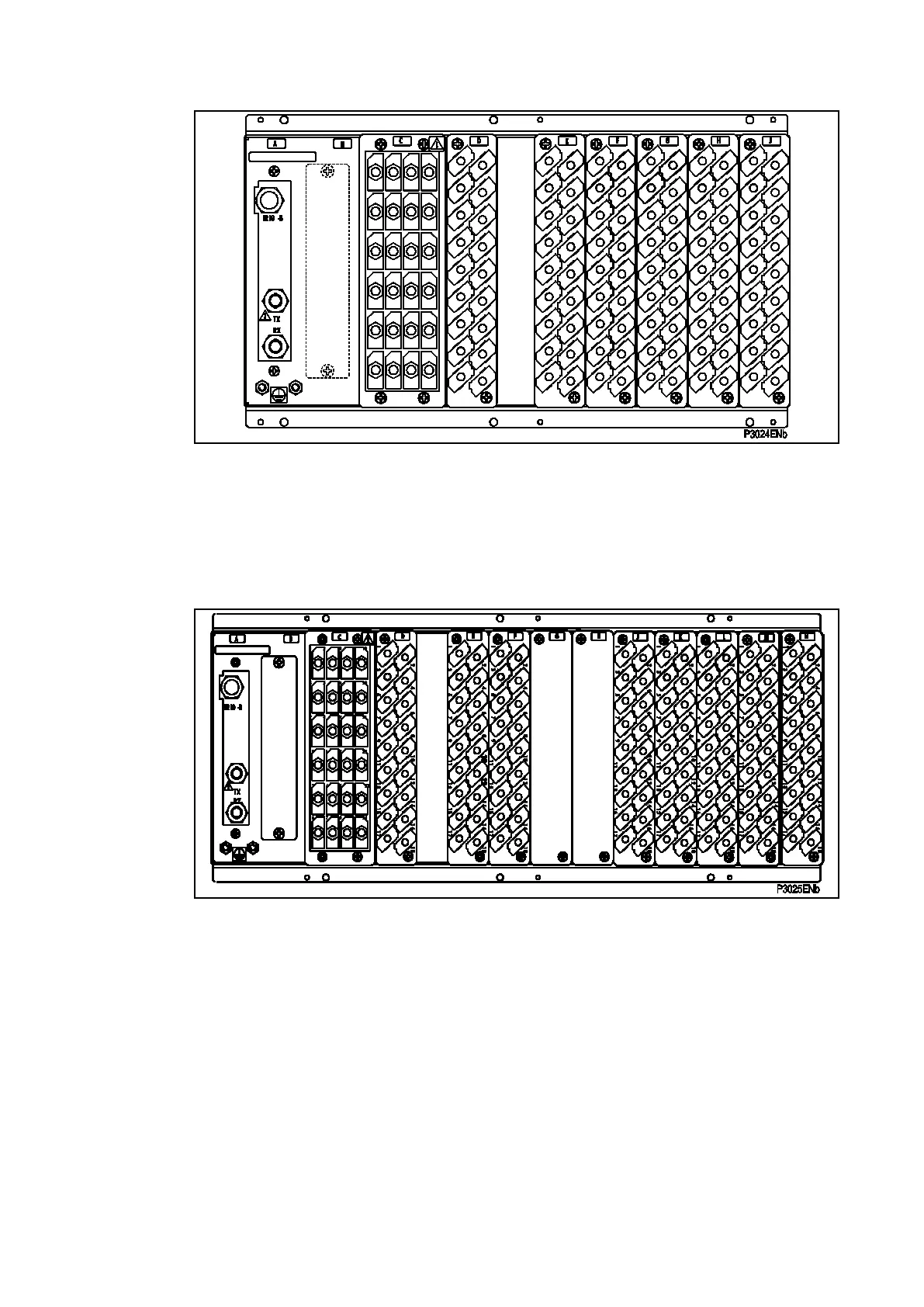
A – Optional board * F – Output relay/High Break board *
B – Optional board * G – Output relay board
C – Current and voltage input board F – Power supply board
D – Opto-input board
E – Opto-input board * = option depending on the model
Figure 2a: P442 Relay rear view (60 TE case)
A – Optional board * H – Relay board
B – Optional board * J – Output relay/High Break board *
C – Current and voltage input board K – Output relay/High Break board *
D – Opto-input board L – Output relay/High Break board *
E – Opto-input board M – Relay board
F – Opto Input board N – Power supply board
G – Relay board * * = option depending on the model
Figure 2b: P444 Relay rear view (80 TE case)
Refer to the wiring diagram in section P44x/EN IN for complete connection details.