– 17 –
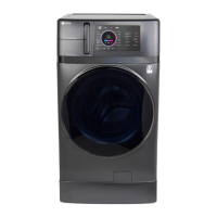
Washer Components
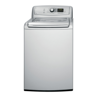
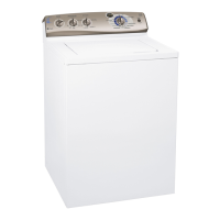
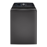
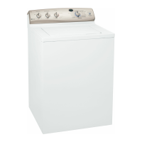
Control Panel
The control panel must be removed to access the
control system components.
To remove the control panel:
1. Remove the 2 Phillips-head screws from the
bottom of the control panel cover.
Control Board Assembly
The control board assembly consists of the power
board and the display/logic board. Both are
attached to the control panel as one unit. Each
board is bonded to a plastic frame. The power
board has a red LED that indicates that the board
is powered and awake. (See Circuit Board Connector
Locator View.) The power and display/logic boards
are available separately.
To remove the control board assembly:
1. Remove the 3 Phillips-head screws from the top
of the control panel cover.
Note: To prevent damage to the control panel and
top cover, place a protective surface over the top
cover.
2. Tilt the control panel toward the front of the
washer to disengage 5 tabs from slots located in
the top cover.
3. Lay control panel face down on the top cover
(Service position).
Tabs
WARNING: Sharp edges may be exposed when
servicing the washer. Use caution to avoid injury.
Wear Kevlar gloves or equivalent protection.
2. Place the control panel in the service position.
(See
Control Panel.)
3. Lift and remove the control panel cover.
4. Pull out and disengage the control cover from 4
tabs on the bottom of the control board.
5. Lift and remove the control cover from the
control board.
Service Position
(Continued Next Page)
Control Cover
Control Panel Cover
 Loading...