12
2.4. Wiring
Moulded-Case Circuit Breaker / Contactor
l GE Power Controls maintenance and service do not apply to damage caused by following
situation:
(1) Damage to the inverter caused by the lack of appropriate molded-case circuit breaker
or a circuit breaker with too large capacity is installed in between the power supply and
the inverter.
(2) Damage to the inverter caused by the serial magnetic contactor, phase advancing capacitor,
or surge-protector in between the inverter and the motor.
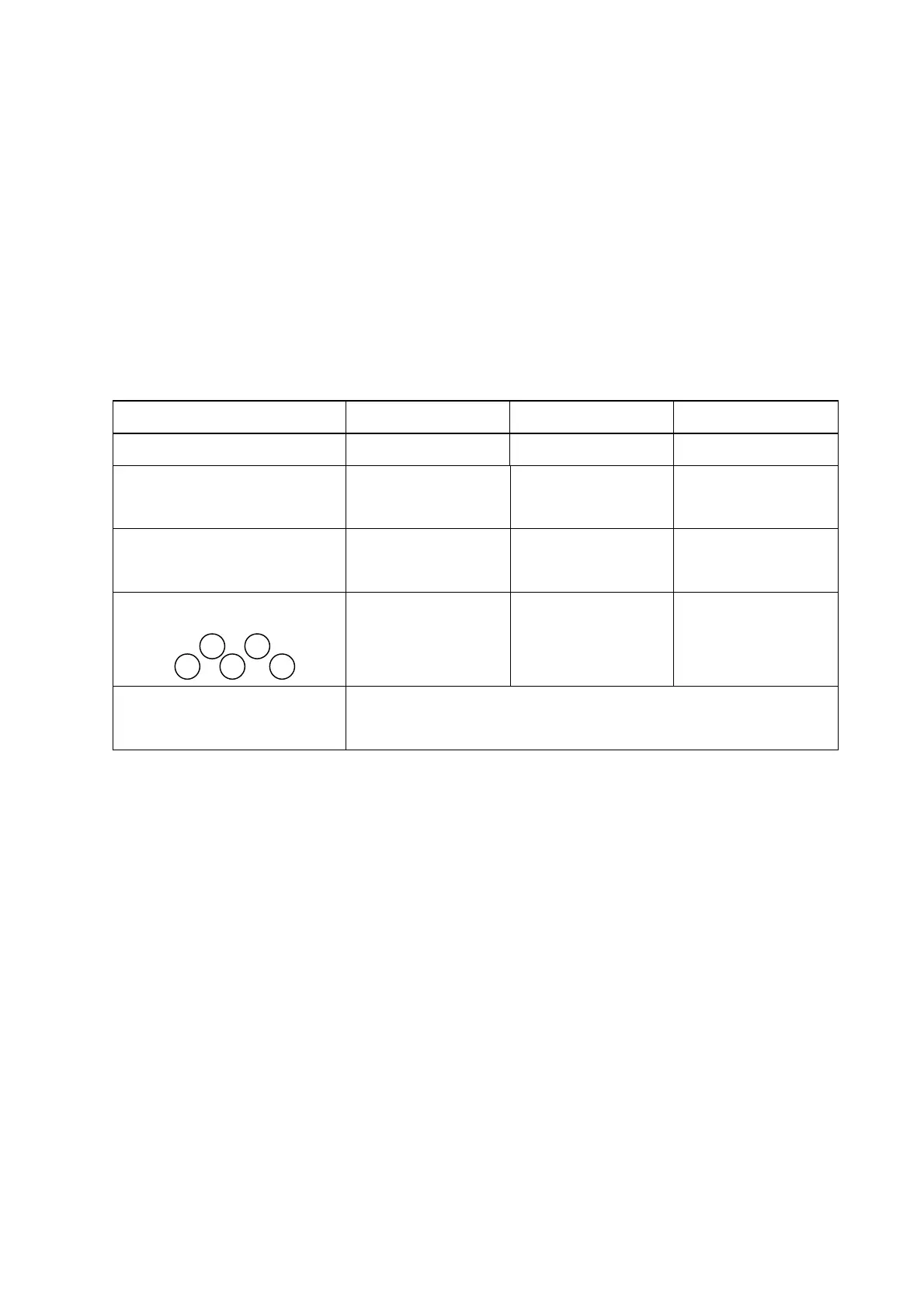
Type No: U20N 0K2, 0K4, 0K7 1K5, 2K2
Type No: U20X 0K7, 1K5, 2K2
Moulded-case circuit breaker
Made by GE
20A
30A
30A
Magnetic Contactor
(MC)
Made by GE
CL00
Made by GE
CL00
Made by GE
CL00
Primary Circuit Terminal (TM1)
Wire dimension
2.5 mm
2
Terminal screw M3
Wire dimension
4 mm
2
Terminal screw M3
Wire dimension
2.5 mm
2
Terminal screw M3
Signal Terminal (TM2)
1~11
Wire dimension 0.75mm
2
(#18 AWG), Terminal screw M3
l Please utilize three-phase squirrel-cage induction motor with appropriate capacity.
l If a inverter is used to drive more than one motor, the total capacity must be smaller
than the capacity of the inverter. Additional thermal relay must be installed in front of
every motor. Use the Fn_18 at 1.0 times of the rated value specified on the motor
nameplate at 50Hz, 1.1 times of the rated value specified on the motor nameplate at 60Hz.
l Do not install phase advancing capacitor, LC, or RC component between the inverter
and the motor.
T3
T1
T2
L1 L2
 Loading...


