EasyManuals Logo

GE VAT20 User Manual

GE VAT20
49 pages
To Next Page IconTo Next Page
To Previous Page IconTo Previous Page
Page #48 background imageLoading...
Page #48 background image
48
4.2. Voltage Current Measurement
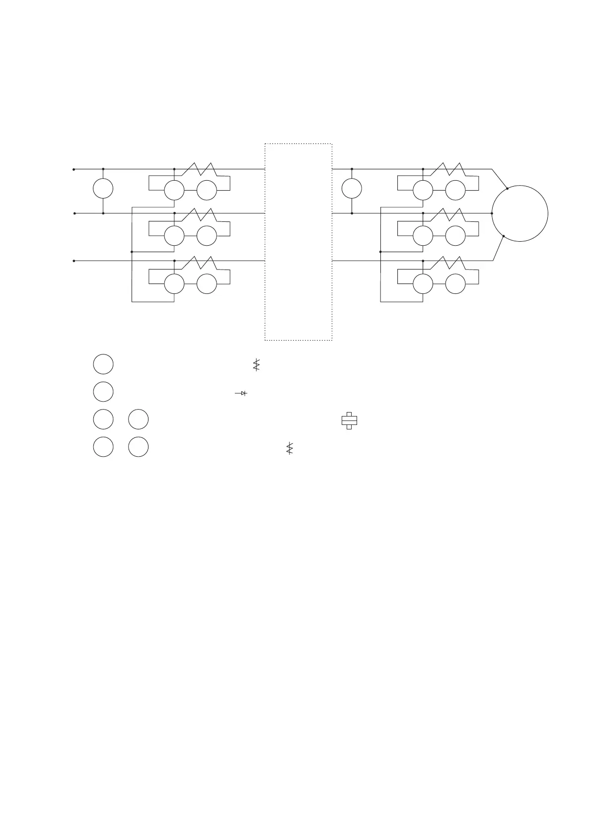
The voltage and current measurement on the primary and secondary side may be different for the
reason of the instrumentation and the high frequency wave. Refer to following diagram for
measurement:
V1
V1
W1 A1
L1 (L)
T1 (U)
L2
T2 (V)
L3 (N)
T3 (W)
SPEED DRIVE
S
U
P
P
L
Y
Moving iron type Voltmeter ( )
W2 A2
W3
A3
V2
M
3ph
W4 A4
W5 A5
W6
A6
V2 Rectifier type Voltmeter ( )
W1 Electrodynamometer type power meterto W6
A1 Moving iron type Ammeter ( )to A6

Questions and Answers:

Question and Answer IconNeed help?

Do you have a question about the GE VAT20 and is the answer not in the manual?

GE VAT20 Specifications

General IconGeneral
BrandGE
ModelVAT20
CategoryInverter
LanguageEnglish

Related product manuals