GE MEDICAL SYSTEMS
D
IRECTION 2300164-100, REVISION 7 VIVID™ 3 PRO/VIVID™ 3 SERVICE MANUAL
7-40 Section 7-3 - Performing Front End (FE) Diagnostics
7-3-8-6 Pencil Probe Test
If a solid black line is observed during scanning, it may indicate a bad transmitting channel. The pencil
probe test checks the transmitting channels associated relays to the pencil probe port. This test is not
for sensitive receiving channels.The test has two phases, namely the open pencil probe test and the
close pencil probe test.
1) Connect a 2D pencil probe.
2) Access the F.B. tab of the FE Diagnostics dialog box, as described in the
Accessing the Front Board
Assembly Options
section, on page 7-25.
3) Trackball to Pulser 1 (High Voltage Power Supply [HVPS] ±80V) or Pulser 2 (Low Voltage Power
Supply [LVPS] ±40V) and press Select.
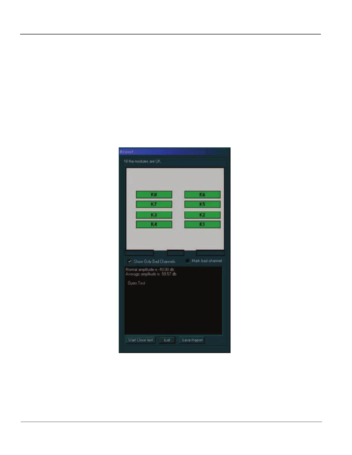
4) Trackball to the Pencil Probe Test button and press Select. The pencil probe test is performed,
and the test results are displayed in the Report dialog box, as shown below:
Figure 7-22 Report Dialog Box - Pencil Probe Test (Open)
Artisan Technology Group - Quality Instrumentation ... Guaranteed | (888) 88-SOURCE | www.artisantg.com
 Loading...


