GE HEALTHCARERAFT VOLUSON E8 / VOLUSON E6
D
IRECTION KTD102576, REVISION 7 DRAFT (AUGUST 23, 2012) SERVICE MANUAL
5-24 Section 5-3 - FrontEnd Processor
Section 5-3
FrontEnd Processor
Voluson E8 / Voluson E6 Front End components described in the sub-sections:
5-3-1 RTF- Probe Connector Board . . . . . . . . . . . . . . . . . . . . . . . . . . . . . . . . . . . . . . . . . . . . .5-25
5-3-2 RTM - Beamformer Motherboard . . . . . . . . . . . . . . . . . . . . . . . . . . . . . . . . . . . . . . . . . .5-27
5-3-3 RSR- Beamformer Receiver Subboards. . . . . . . . . . . . . . . . . . . . . . . . . . . . . . . . . . . . .5-28
5-3-4 RST- Beamformer Transmitter Subboards . . . . . . . . . . . . . . . . . . . . . . . . . . . . . . . . . . .5-28
5-3-5 RSW - CW-Doppler Board (optional) . . . . . . . . . . . . . . . . . . . . . . . . . . . . . . . . . . . . . . .5-29
5-3-6 RTK - Motherboard . . . . . . . . . . . . . . . . . . . . . . . . . . . . . . . . . . . . . . . . . . . . . . . . . . . . .5-29
5-3-7 RFI - Radio Frequency Interface “Controller” Board . . . . . . . . . . . . . . . . . . . . . . . . . . . .5-30
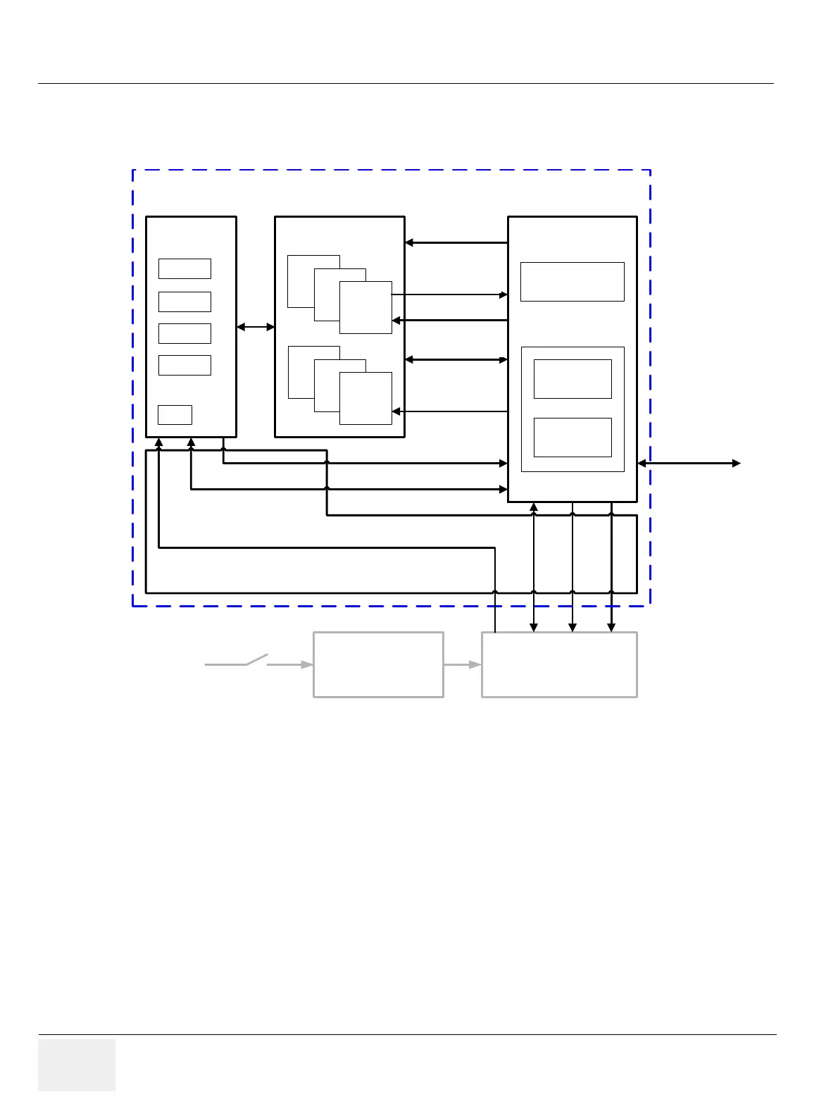
Figure 5-5 Front End Processor - Block diagram
RFI
RF-Interface
RSR
RST
RTM Rx/Tx
Motherboard
RTP Secondary
Power Supply
Probe / Code Select, serial 10 Mb/s
Hall, Probe Code
1
, ...
RTK Mainboard
PCI 32 Bit
33 MHz,
132 MB/s
RTN Primary
Power Supply
RTF
ProbeConnect
FPGA
RSR
RSR
RST
RST
BF Rx Data, LVDS, 14 pairs
50MHz Clock
Rx coeff. LVDS, 8 pairs
600Mb/s
BF Config (CW Gain, Test, ...)
Serial 10 Mb/s
Tx coeff. LVDS, 8 pairs,
600 Mb/s
FPGA Config. Serial 50MHz
I²C Bus
Serial I/F to Motor
Power Drivve
CPP Analog I/O
FrontEnd
DSP Motor control
(Digital Signal Processor)
Interface
Processing
Mains
Power
Voltage Supply: +3,3V, -3,3V, 2,0V, TxPower 1, TxPower 2
FPGA