Wiegand Interface Unit Four State (WIU-4)
Installation Manual
12
J7: Reserved
The 2-pin connector, J7, is reserved. A jumper is installed by
default across pins 1 and 2.
J8: Micro interface connector
The 4-pin connector, J8, is the Micro interface connector.
J9: Reserved
The 2-pin connector, J9, is reserved.
J10: Door strike relay connectors
The 5-pin connector, J10, is the door strike relay connection.
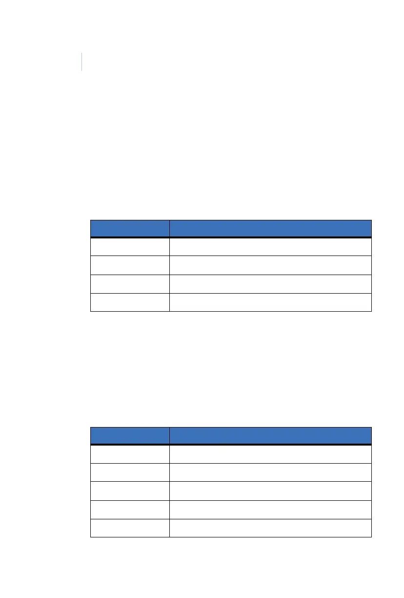
Table 3. J8 Micro interface connector
PIN Description
1 Power 12 VDC (power for WIU-4)
2 Ground
3Door DO
4 Reader F/2F data
Table 4. J10 Door strike relay connector
PIN Description
1 Relay power (Source)
2 Relay power (Return)
3 Normally closed (NC) contact
4Not used
5 Normally open (NO) contact