18
D
GB
F
E
96416-08.2020-DGbFEIRu
Fig.11
0
Datum Name
Datum
Bearb.
Gepr.
Norm
1
20.02.2009
bauknecht
04.08.2017
Urspr.
2
3
4
PW INT69 HG44/66
5 6 7
BOCK COMPRESSORS
8
=
+
9
Bl.
6.c Bl.
6.a
2
Anschlußkasten Verdichter
BT1
INT69
QA1
L1 L2 L3 N PE
FC1.1
I>
I>
I>
QA2
1U1
1V1
1W1
PE
EC1
M
Y/YY
2U1
2V1
2W1
FC1.2
I>
I>
I>
QA3
FC1.1
FC1.2
FC2
SF1
BP2
P>
QA2
BP3
P
QA2
KF1
KF1
6.c.8
QA2
L1.1
L2.1
L3.1
L1.2
N
PE
QA3
BT3
BT2
Θ
1112 14
L N B1 B2
12
11
10
9
8
7
6
5
4
3
2
1
50%
50%
Compressorterminalbox
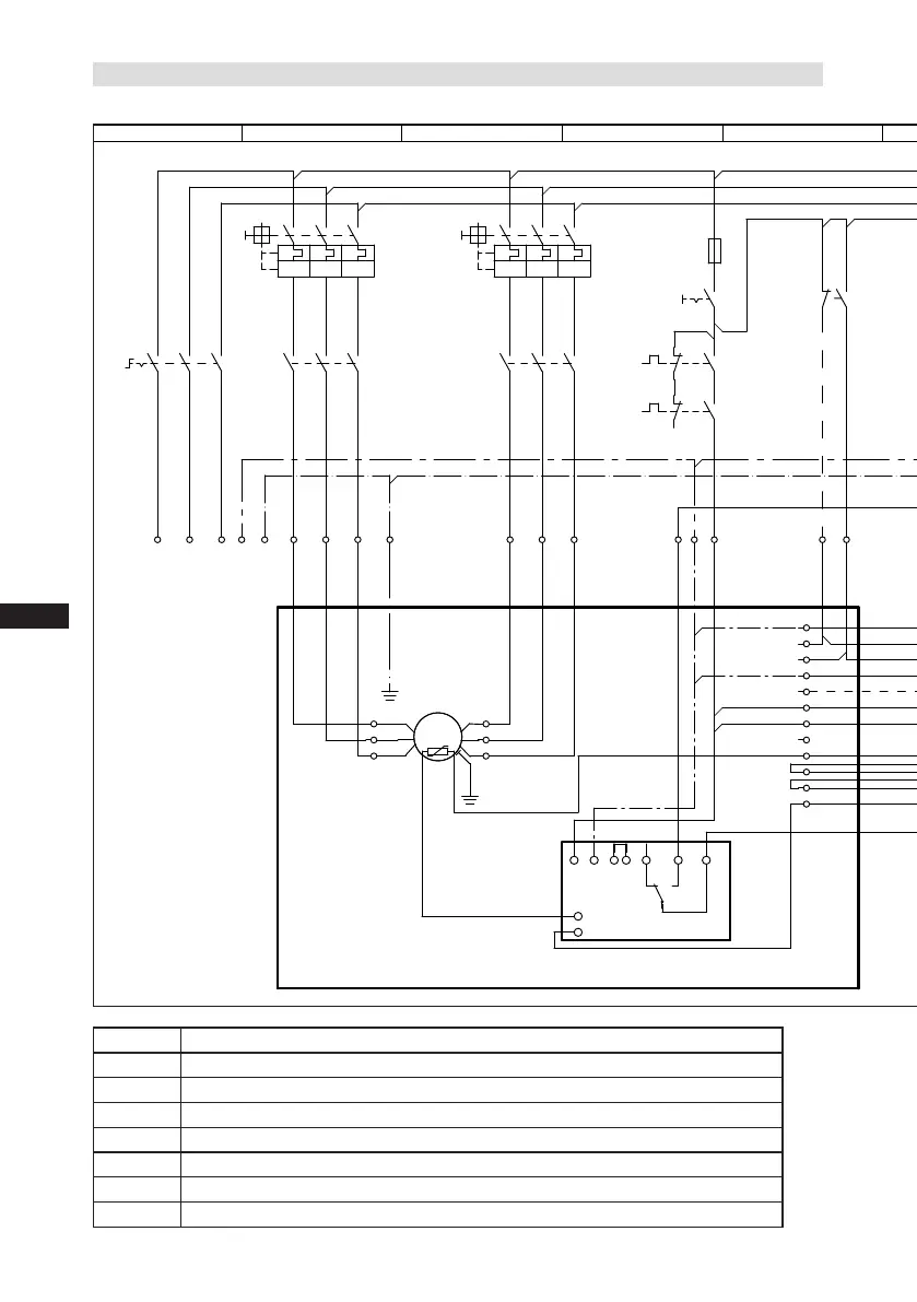
7.3 Basiccircuitdiagramforpartwindingstartwithstandardmotor
BP2 Highpressuresafetymonitor
BP3
Safetychain(high/lowpressuremonitoring
)
BT1
Coldconductor(PTCsensor)motorwinding
BT2 Thermalprotectionthermostat (PTCsensor)
BT3 Releaseswitch(thermostat)
DELTA-PII OildifferentialpressuresensorDELTA-PII(accessorie)
EB1
Oilsumpheater
EC1 Compressormotor

 Loading...