26
D
GB
F
E
96416-08.2020-DGbFEIRu
7 | Electrical connection
7.10Oilsumpheater(accessories)
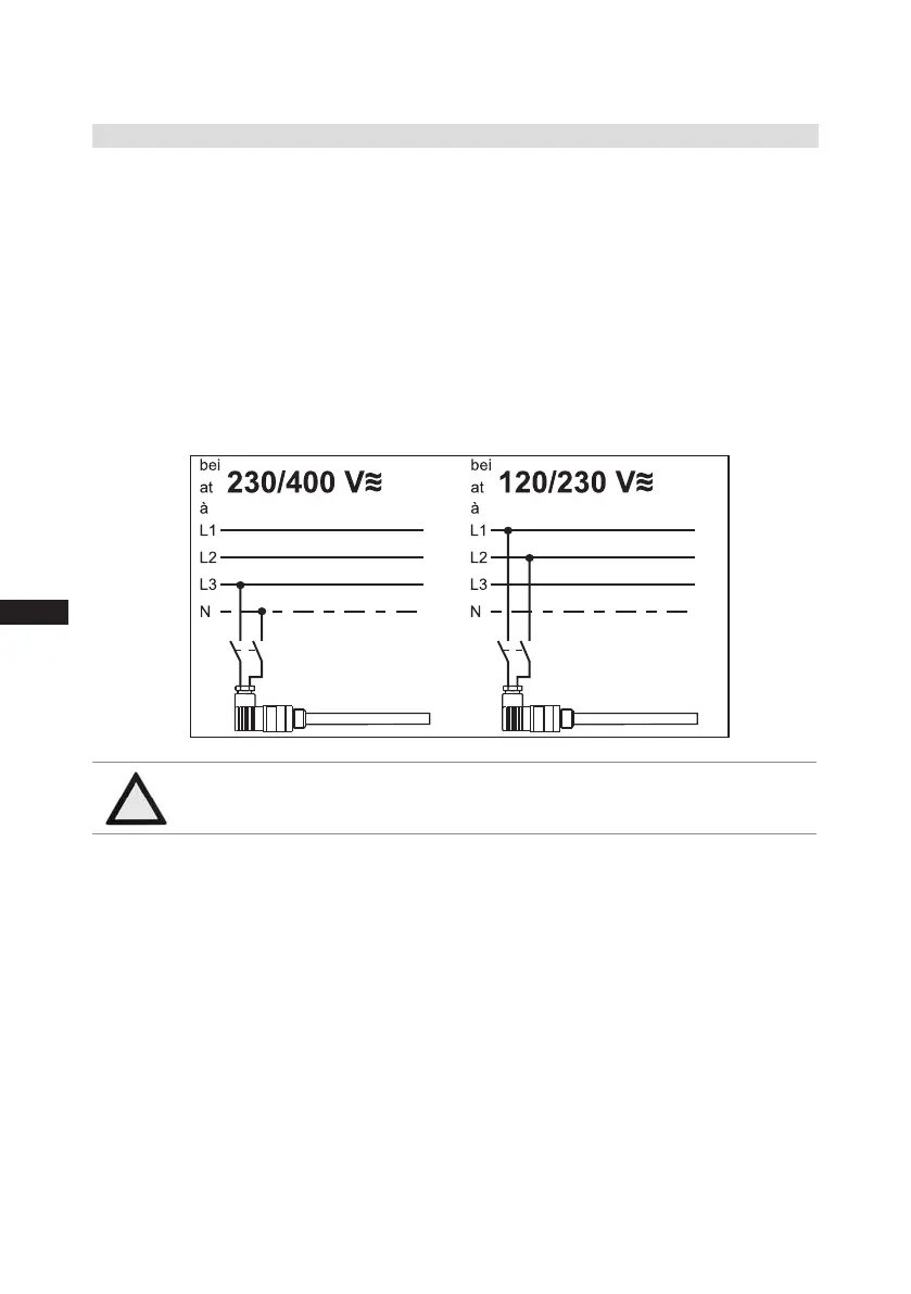
Anschlussschema für Ölsumpfheizung
Connection diagramm for oil sump heater
Plan de raccordement pour résistance de carter d‘huile
09983- 10.01-DGBF
D
GB
F
Whenthecompressorisatastandstill,refrigerantdiffusesintothelubricatingoilofthecompressors
housing,dependingonpressureandambienttemperature.Thisreducesthelubricatingcapacityof
theoil.Whenthecompressorstartsup,therefrigerantcontainedintheoilevaporatesoutthroughtthe
reductioninpressure.Theconsequencescanbefoamingandmigrationoftheoil,causingoilshocks
undercertaincircumstances.
Operation:Theoilsumpheateroperateswhenthecompressorisatastandstill.Whenthecompres-
sorstartsup,theoilsumpheaterswitchesoffagainautomatically.
Connection:Theoilsumpheatermustbeconnectedviaanauxiliarycontact(orparallelwiredauxili-
arycontact)ofthecompressorcontactortoaseperateelectriccircuit.
El.data:230V-1-50/60Hz,160W.
Fig.16
ATTENTION Connectiontothecurrentpathofthesafetycontrolchainisnot
permitted.

 Loading...