EasyManuals Logo

GEA Bock HG8 Series User Manual

GEA Bock HG8 Series
38 pages
To Next Page IconTo Next Page
To Previous Page IconTo Previous Page
Page #12 background imageLoading...
Page #12 background image
12
D
GB
F
E
I
Ru
09790-02.2018-DGbFEIRu
4| Compressor assembly
Rigid
fixed point
As short as
possible
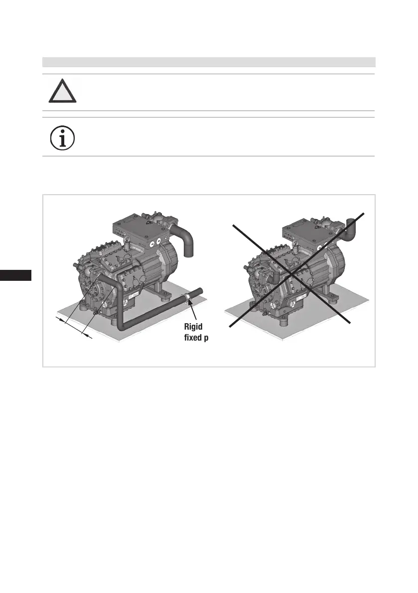
4.5 Laying suction and pressure lines
A rule of thumb:
Alwayslaytherstpipesectionstartingfromtheshut-offvalvedownwards
and parallel to the drive shaft.
ATTENTION Improperly installed pipes can cause cracks and tears, the result
being a loss of refrigerant.
INFO Proper layout of the suction and discharge lines directly after
the compressor is integral to the system’s smooth running and
vibration behaviour.
Fig. 15

Questions and Answers:

Question and Answer IconNeed help?

Do you have a question about the GEA Bock HG8 Series and is the answer not in the manual?

GEA Bock HG8 Series Specifications

General IconGeneral
BrandGEA
ModelBock HG8 Series
CategoryAir Compressor
LanguageEnglish

Related product manuals