21
09665-08.2018-Gb
8 I Electromagnetic coupling
Assembly instruction for electromagnetic coupling
For the drive of A/C compressors in buses, mainly electromagnetic couplings are used. The followings assembly instructions for coupling type
LA 16 is representative for couplings which are mounted onto the front bearing ange of the compressor.
Assembly instruction for electromagnetic coupling type LA 16
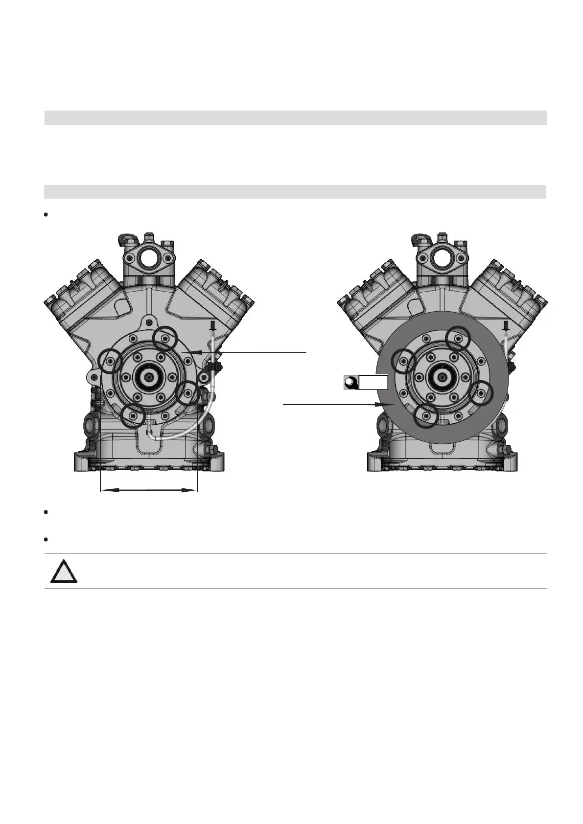
The front bearing ange has a location face Ø 148 h8 for tting the solenoid of the electromagnetic coupling (see Fig. 8).
Fig. 8
Front bearing ange
Magnetic eld
Fig. 9
148 h8
For tting the solenoid (1) remove the four M8x25 cylinder screws (2) on the bearing ange (indicated with circles and arrows, Fig. 8 page
21 and Fig. 10 page 22).
Fit the solenoid onto the location seat and fasten it again with the four M8x25 cylinder screws (Fig. 9).
ATTENTION Use only M8x25 screws! Otherwise, serious damages may occur on the electromagnetic coupling and the
compressor. Observe the screw tightening torque!
85 Nm
 Loading...