Therefore, for all Grasso two-stage types a fast pull- down electric capacity
control system has been developed, which allows the compressors to be started
with two or more HP cylinders in operation and which includes one or more part-
load steps with volume ratio ϕ = 1.
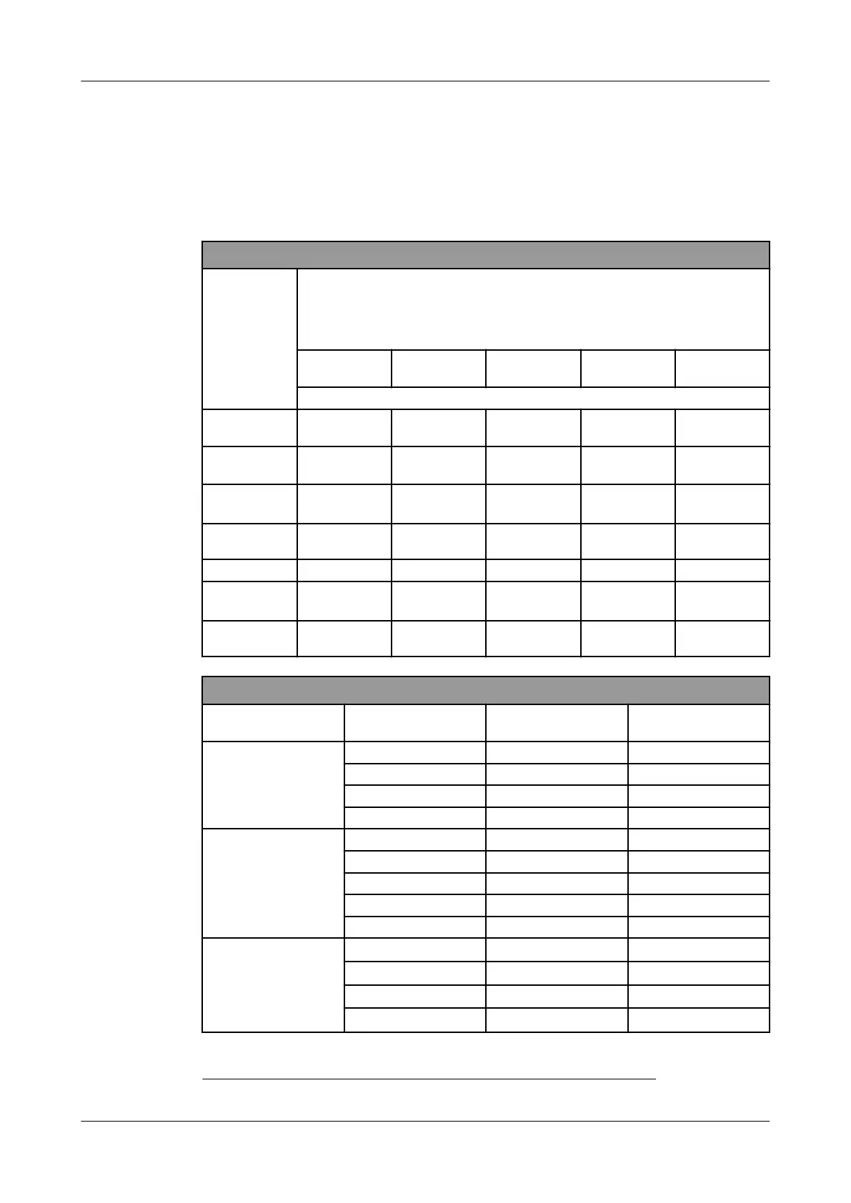
4.4 DIAGRAMS SINGLE STAGE AND BOOSTER
Solenoid valve/cylinder numbering for electric capacity control
Compressor type
Solenoid
UNL
NO
No. 1
NC
No. 2
NC
No. 3
NC
No. 4
NC
Cylinder number / solenoid valves
V 300 &
V 700
1 2 3 4 -
V 450 &
V 1100
(3+4) 2 (5+6) 1 -
V 600, Before July
2019
(5+6) 7 8 (2+4) (1+3)
V 600 From July
2019
(5+6) 7 8 (1+2) (3+4)
V 1400 (5+6) 7 8 (2+4) (1+3)
V 1800 Before Sept.
2014
(7+8) 5 6 (9+10) (1+2+3+4)
V 1800 From
Sept. 2014
(5+7+8) (9+10) (1+2) (3+4) 6
Capacity control steps
Compressor
type
Capacity %
17
Cylinders Solenoids
V 300
&
V 700
25 1 -
50 1 + 2 1
75 1 + 2 + 3 1 + 2
100 1 + 2 + 3 + 4 1 + 2 + 3
V 450
&
V 1100
33 (3+4) -
50 (3+4) + 2 1
67 (3+4) + (5+6) 2
83 (3+4) + (5+6) + 1 2 + 3
100 (3+4) +2 + (5+6) + 1 1 + 2 + 3
V 600
Before July 2019
25 (5+6)
-
37 (5+6) + 8 2
50 (5+6) + 8 + 7 1 + 2
62 (5+6) + 8 + (1+3) 2 + 4
17 Refer to the swept volume expressed as a percentage of the full-load swept volume
APPENDIX; Product Information (PI)
DIAGRAMS SINGLE STAGE AND BOOSTER
0089288_imm_v_english_19
07.04.2021 55