4.5 DIAGRAMS TWO STAGE
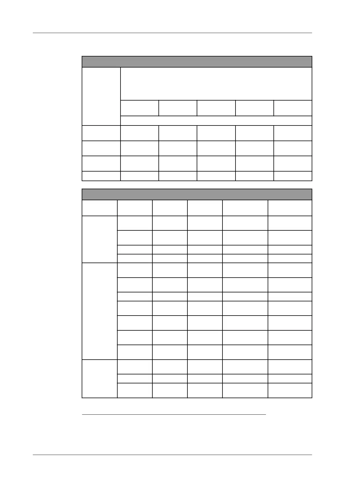
Solenoid valve/cylinder numbering for electric capacity control
Compressor
type
Solenoid
UNL
NO
18
No. 1
NC
No. 2
NC
No. 3
NC
No. 4
NC
Cylinder number
19
/ solenoid valves
300T &
700T
[4
hp
]
1 2 3 -
450T &
1100T
[4
hp
]
1 2, 3
5, [6
hp
]
-
600T &
1400T
[6
hp
]
1, 2 3
4, [8
hp
]
5, 7
1800T
[6
hp
]
1, 2
7, [8
hp
], 9
5
3, 4, [10
hp
]
Capacity control steps
Compressor
type
Capacity %
20
Cylinders Solenoids
Qty HP / Qty LP
cylinders
21
Remark
22
)
300T
&
700T
0 [4] - 0.0
Starting only/ Fast
pull down
33 1 + [4] 1 1.0
Starting only/Fast
pull down
67 1 + 2 + [4] 1 + 2 2.0 -
100 1 + 2 + 3 + [4] 1 + 2 + 3 3.0 -
450T
&
1100T
0 [4] - 0.0
Starting only/Fast
pull down
25 1 + [4] 1 1.0
Starting only/Fast
pull down
50 (2 + 3) + [4] 2 2.0 -
50
1 + [4] +(5 +
[6])
1 + 3 1.0
Starting only/Fast
pull down
75
1 + (2 + 3) +
[4]
1 + 2 3.0 -
75
(2 + 3 )+ [4] +
(5 + [6])
2 + 3 1.5
Starting only/Fast
pull down
100
1+ 2 + 3 + [4]
+ (5 + [6])
1 + 2 + 3 2.0 -
600T
&
1400T
0 [6] - 0.0
Starting only/Fast
pull down
33 (1 + 2) + [6] 1 2.0 -
33
3 + [6] + (4 +
[8])
2 + 3 1.0
Starting only/Fast
pull down
18 UNL, Unloaded start
19 Numbers between brackets [] are HP cylinders
20 Refer to the swept volume expressed as a percentage of the full-load swept volume of the LP cylinders
21 Each phi has its own field of application! Refer Page 57
22 For starting up procedure, refer Section 4.3, Page 53
APPENDIX; Product Information (PI)
DIAGRAMS TWO STAGE
0089288_imm_v_english_19
07.04.2021 57


 To Next Page