48 ADL500 • Quick installation guide - Specifications and connection
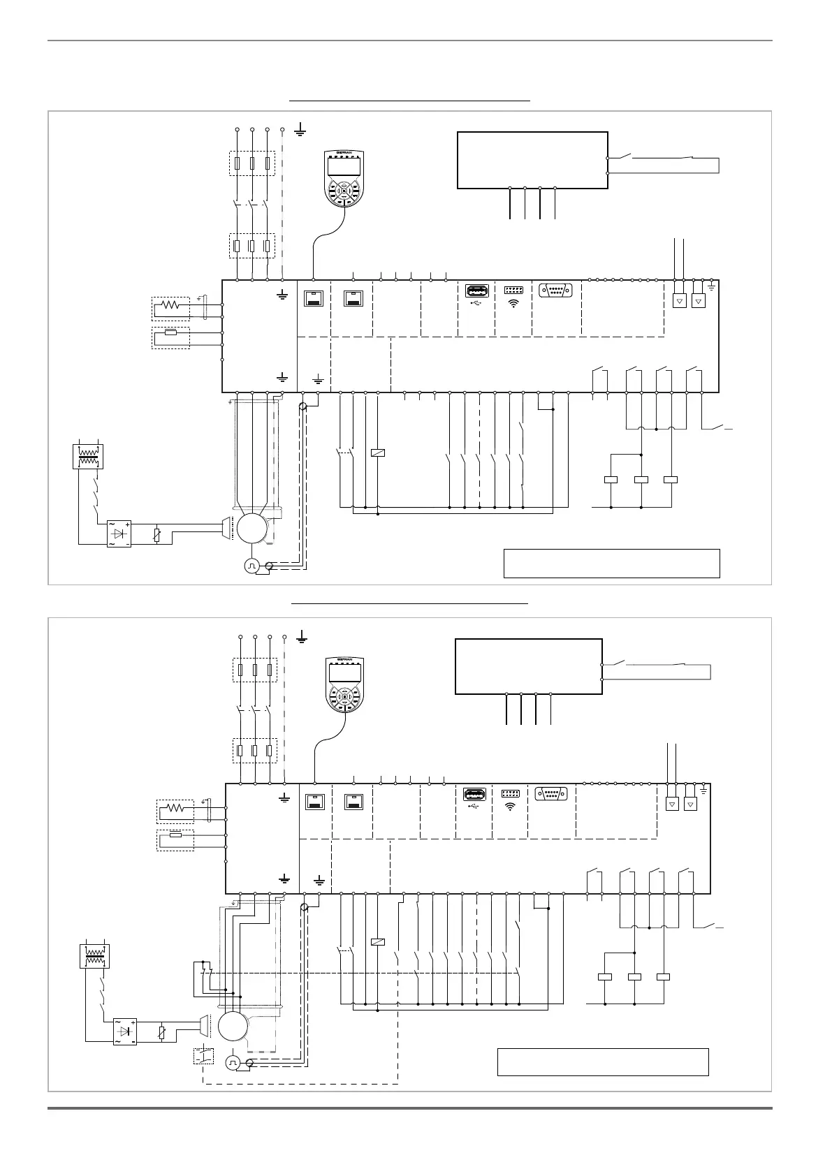
Diagram of a lift system complying with EN 81-20 5.9.2.5.3 d,without contactors and STO integrated safety function
(EN61800-5-2- SIL3).
Figure 7.9.8-A: Contactorless connections (Asynchronous motor)
SYSTEM CONTROL UNIT
Commands
Contactor
check-up
K4 K3M
MltSpd S1
Emergency mode
MltSpd S0
StartFwdCmd
StartRevCmd
K3M
K4 (*)
Safety
chain
L1
K2M K3M BR
Emergency
Failure
K2M
K4
(*): K4 and CONTACTORLESS OK must be checked by control unit
- PAR 11088 Contactorless enable must be turn ON to configure
contactorless OK output.
M
3
~
BRAKE
K2M
K3M
BR
TRAFO
A1
A2
A1
A2
A1
A2
1
2
K1M
3
4
5
6
DC CHOKE
L2
(ADL550: 4 to 22kW)
ADL550
U1
V1 W1
U2
V2
W2
DOOR
CAN
DI8
DI7
DI6
DI5
DI4
DI3
DI2
DI1
ENHW
DICM
0VOUT
24VOUT
L1 L2 L3
KEYPAD
ETH-PC
T1 T2 T3
1 2 3 4 5 6 7 8 9 10 11 12
PE
PE
50
51
SH
H
L
D
C
BR1
BREAKING
RESISTOR
BR2
BRAKE
CONTACTOR
OK
DRIVE
52
53
54
55
CONTACTOR
RUN
56
57
3 Phase Mains
(optional)
EN+
EN-
XE
XER
PE
OK1
OK2
C1
OPTIONAL
AC CHOKE
L1
OPTIONAL
F1
SFTY-STO
+24V (EXT)
+24V
0
EXP-DCP
(optional)
USB 2.0
DI4X
1
DI3X
2
DI2X
3
DI1X
4
DICM
5
EXP-4DI+2RO
(optional)
RO_5O
1
RO_5C
2
RO_6O
3
RO_6C
4
-
-
+
+
MOT-
MOT+
AI_1P
AI_1N
Motor PTC
OPTIONAL
OPTIONAL
1 2 3 4
Figure 7.9.8-B: Contactorless connections (Synchronous motor)
SYSTEM CONTROL UNIT
Commands
Contactor
check-up
K4
CONTACTORLESS
(*)
OK
M
3
~
Contactorless
Enable
K2M
K3M
MltSpd S1
MltSpd S2
Emergency mode
MltSpd S0
StartFwdCmd
StartRevCmd
Safety
chain
L1
K2M
K3M BR
BRAKE
K2M
K3M
BR
TRAFO
FBR
K3M
Emergency
Failure
K3M
Safety
chain
K2M
K4
(*): K4 and CONTACTORLESS OK must be checked by control unit
- PAR 11088 Contactorless enable must be turn ON to configure
contactorless OK output and Contactorless enable digital input (DI7).
BrakeFbk
K4
A1
A2
A1
A2
A1
A2
1
2
K1M
3
4
5
6
DC CHOKE
L2
(ADL550: 4 to 22kW)
ADL550
U1
V1 W1
U2
V2
W2
DOOR
CAN
DI8
DI7
DI6
DI5
DI4
DI3
DI2
DI1
ENHW
DICM
0VOUT
24VOUT
L1 L2 L3
KEYPAD
ETH-PC
T1 T2 T3
1 2 3 4 5 6 7 8 9 10 11 12
PE
PE
50
51
SH
H
L
D
C
BR1
BREAKING
RESISTOR
BR2
BRAKE
CONTACTOR
OK
DRIVE
52
53
54
55
CONTACTOR
RUN
56
57
3 Phase Mains
(optional)
EN+
EN-
XE
XER
PE
OK1
OK2
C1
OPTIONAL
AC CHOKE
L1
OPTIONAL
F1
SFTY-STO
+24V (EXT)
+24V
0
EXP-DCP
(optional)
USB 2.0
DI4X
1
DI3X
2
DI2X
3
DI1X
4
DICM
5
EXP-4DI+2RO
(optional)
RO_5O
1
RO_5C
2
RO_6O
3
RO_6C
4
-
-
+
+
MOT-
MOT+
AI_1P
AI_1N
Motor PTC
OPTIONAL
OPTIONAL
1 2 3 4