78 ADL500 • Quick installation guide - Specifications and connection
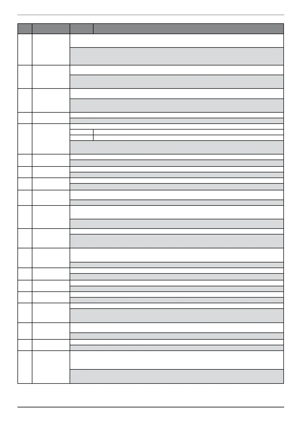
Index Error message shown
on the display
Sub-code Description
13 Drive overload Condition: Drive overload alarm.
- The inverter output current has exceeded the allowed overload value.
- The overload cycle has exceeded the allowed values.
Solution:
- Check that the load is not excessive.
- Check that accelerations are not excessive.
- Check that the overload cycle is within allowed limits.
14 Motor overload Condition: Motor overload alarm.
The current absorbed during operation is greater than that specified on the motor data plate.
Solution:
- Reduce the motor load.
- Increase the size of the motor.
15 Bres overload Condition: Braking resistor overload alarm.
The current absorbed by the resistor is greater than the rated current.
Solution:
- Check the size of the braking resistor.
- Check the condition of the braking resistor.
16 Phase loss Condition: Power phase loss alarm.
Solution: Check the mains voltage and whether any protections upstream of the drive have been tripped.
17 Opt Bus fault Condition: Error in the configuration stage or communication error.
XXX0H-X If the first digit to the left of “H” in the alarm sub-code is equal to 0, the error relates to a communication problem.
XXXXH-X If the first digit to the left of “H” in the alarm sub-code is other than 0, the error relates to a configuration problem.
Solution: For configuration errors, check the configuration of the Bus communication, Bus type, Baudrate, address. parameter setting
For communication errors verify wiring, resistance of terminations, interference immunity, timeout settings.
For more details reference should be made to the datasheet of the bus being used.
18 Opt 1 IO fault Condition: Error in the communication between Regulation and I/O expansion card.
Solution: Check that it has been inserted correctly, see section "A.1 - Optional cards" on page 87.
19 Precharge fault Condition:
Solution:
20 Opt enc fault Condition:
Solution:
21 External fault Condition: External alarm present.
A digital input has been programmed as an external alarm, but the +24V voltage is not available on the terminal.
Solution: Check that the terminal screws are tight
22 Speed fbk loss Condition: Speed feedback loss alarm.
The encoder is not connected, not connected properly or not powered: verify encoder operation by selecting the PAR 260 Motor speed parameter in the
MONITOR menu.
Solution:
See parameter 2172 SpdFbkLoss code for information about the cause of the alarm and chapter 10.2 Speed fbk loss [22] alarm
23 Overspeed Condition: Motor overspeed alarm. The motor speed exceeds the limits set in the PAR 4540 parameter.
Solution:
- Limit the speed reference.
- Check that the motor is not driven in overspeed during rotation.
24 Speed ref loss Condition: Speed reference loss alarm; occurs if the difference between the speed regulator reference and the actual motor speed is more than
100 rpm. This condition occurs because the drive is in the current limit condition. It is only available in the Flux Vect OL and Flux Vect CL mode (see PAR
4550).
Solution: Check that the load is not excessive.
25 Emg stop alarm Condition:
Solution:
26 Power down Condition: The drive was enabled with no supply voltage at the power section.
Solution: Check drive power supply.
27 Phaseloss out Condition: Output phase loss.
Solution: Check Drive/motor connection.
28 OV safety Condition: Safety status alarm caused by Overvoltage situations.
Solution: the firmware attemps to reset the card automatically.
If the condition is removed (the alarm cleared message is displayed) the alarm can be reset and the drive restarted by deactivating and reactivating Enable
and Start.
29 Safety failure Condition: The state of the "safety function" is communicated to the regulation card via 2 digital inputs: SAFETY_ON (pin P1.8) and SAFETY_EN (pin
P1.9)
Solution: Switch the drive off and then back on. If the error persists, contact the technical service centre.
30 Mot phase loss Condition: Output phase loss.
Solution: Check Drive/motor connection.
31 Ropes change This may occur in two conditions:
• the drive continues to run but the rope usage threshold set in parameter 3404 Ropes change thr has been reached;
• the drive finishes the current travel and then locks because parameter 3414 Direction counter has reached 0 (corresponding to parameter 3412
Ropes usage = 100%).
Solution: replace the ropes.
By switching the drive off and back on you can run a single travel to bring the car to a better position for the procedure.
After you have changed the ropes, reset the direction change counter to eliminate the lock condition.

 Loading...


