8 ADV20 QS, V1.02
Italiano English
Terminal
Symbol
Terminal Function
Factory Settings (NPN mode)
ON: Connect to DCM
+24V DC Voltage Source +24VDC, 50mA used for PNP mode.
DCM Digital Signal Common
Common for digital inputs and used for NPN
mode.
RA
Multi-function Relay output
(N.O.) a
RB
Multi-function Relay output
(N.C.) b
RC Multi-function Relay common
Resistive Load:
5A(N.O.)/3A(N.C.) 240VAC
5A(N.O.)/3A(N.C.) 24VDC
Inductive Load:
1.5A(N.O.)/0.5A(N.C.) 240VAC
1.5A(N.O.)/0.5A(N.C.) 24VDC
Refer to Pr.03.00 for programming
+10V Potentiometer power supply +10VDC 3mA
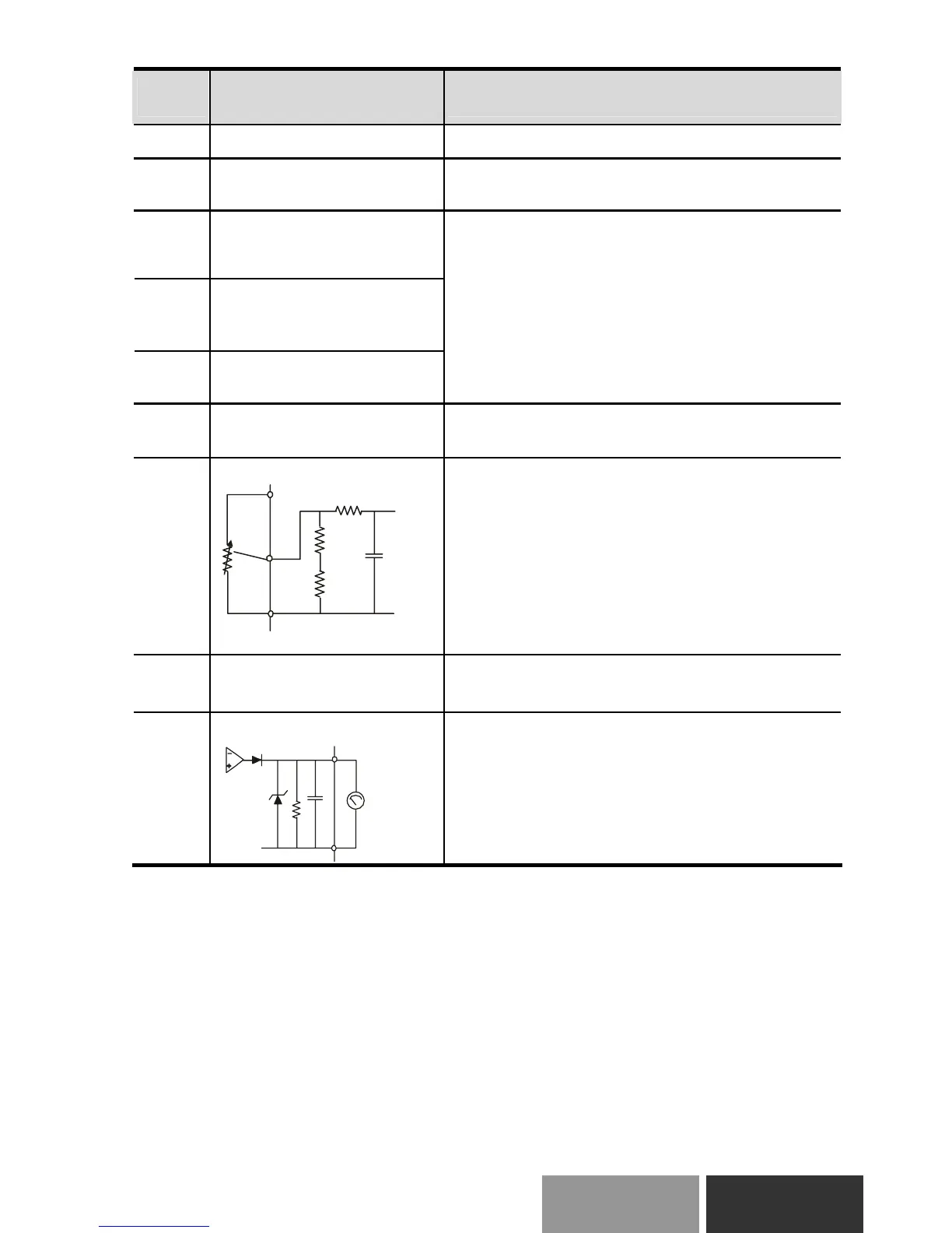
AVI
Analog voltage Input
ACM
AVI
+10V
internal circuit
AVI circuit
Impedance: 47kΩ
Resolution: 10 bits
Range: 0 ~ 10VDC / 4 ~ 20mA =
0 ~ Max. Output Frequency
(Pr.01.00)
Selection: Pr.02.00, Pr.02.09, Pr.10.00
Set-up: Pr.04.14 ~ Pr.04.17
ACM
Analog control signal
(common)
Common for AVI/ACI and AFM
AFM
Analog output meter
 Loading...