1S9STOEN_26-5-17_ADL300_STO_STO Pag. 10/30
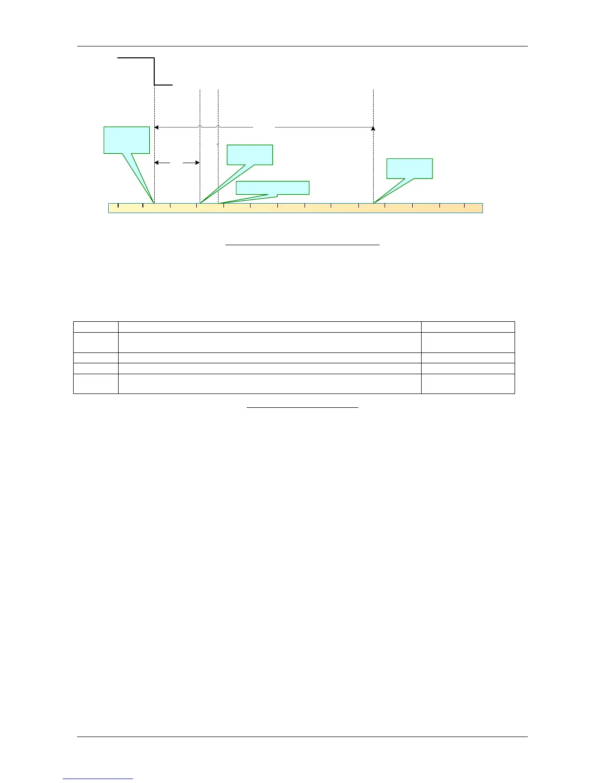
Torque On
signal
Ttoff
Tfbon
Tmotoff
Feedback relay activated
Motor safely
stopped
Motor Torque
Off
One
/both
control signals
disabled
Figure 2 Time event diagram for STO function.
- T
toff
time from control signal disabled to STO function activation
- T
fbon
time from STO function activation to feedback signal changing state
- T
motoff
time from STO function activation to motor stop: depends on motor/load inertia
Time between ENABLE/SAFETY ENABLE signal deactivation and safety
channel activation (the same for both ENABLE and SAFETY ENABLE)
Time between SAFETY ENABLE and SAFETY FEEDBACK change of status
Time between ENABLE signal activation and drive activation (Drive Active)
In case SAFETY ENABLE is issued before ENABLE maximum allowed time
before system goes into interblock
8
Table 2 Safety Intervention times.
Looking at the Enable signals evolving dynamically in time, the allowed input conFiguretions are
less than those highlighted in Table 1: in order to prevent pwm pulses to be applied suddenly
ENABLE signal will always follow SAFETY ENABLE or, at least be applied before 4ms within it.
Should ENABLE come first before SAFETY ENABLE, ADL drive goes into interlock block and it
will be necessary to disable and issue ENABLE high again in order to reactivate ADL.
Following figures are describing the dynamics of STO. function:
 Loading...


