ADV50 QS, SW-PW V1.11 / CTL V2.11 15
Italiano English
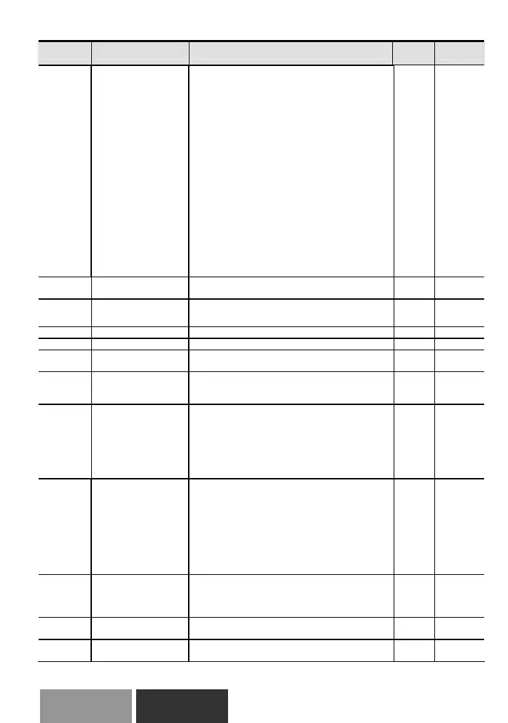
Pr. Explanation Settings
Factory
Setting
NOTE
03.01
Multi-function Output
Terminal MO1
5: Base-Block (B.B.) indication
6: Low-voltage indication
7: Operation mode indication
8: Fault indication
9: Desired frequency attained
10: Terminal count value attained
11: Preliminary count value attained
12: Over Voltage Stall supervision
13: Over Current Stall supervision
14: Heat sink overheat warning
15: Over Voltage supervision
16: PID supervision
17: Forward command
18: Reverse command
19: Zero speed output signal
20: Warning(FbE,Cexx, AoL2, AUE, SAvE)
21: Brake control (Desired frequency attained)
22: Drive ready
23: Desired frequency 2 attained
1
03.02
Desired Frequency
Attained
0.00 to 600.0Hz 0.00
a03.03
Analog Output Signal
Selection (AFM)
0: Analog frequency meter
1: Analog current meter
0
a03.04 Analog Output Gain 1 to 200% 100
03.05 Terminal Count Value 0 to 9999 0
03.06
Preliminary Count
Value
0 to 9999 0
03.07
EF Active When
Terminal Count Value
Attained
0: Terminal count value attained, no EF display
1: Terminal count value attained, EF active
0
03.08 Fan Control
0: Fan always ON
1: 1 minute after AC motor drive stops, fan will
be OFF
2: Fan ON when AC motor drive runs, fan OFF
when AC motor drive stops
3: Fan ON when preliminary heatsink
temperature attained
0
03.09
The Digital Output
Used by PLC
Read only
Bit0=1:RLY used by PLC
Bit1=1:MO1 used by PLC
Bit2=1:MO2/RA2 used by PLC
Bit3=1:MO3/RA3 used by PLC
Bit4=1:MO4/RA4 used by PLC
Bit5=1:MO5/RA5 used by PLC
Bit6=1:MO6/RA6 used by PLC
Bit7=1:MO7/RA7 used by PLC
##
03.10
The Analog Output
Used by PLC
Read only
Bit0=1:AFM used by PLC
Bit1=1: AO1 used by PLC
Bit2=1: AO2 used by PLC
##
03.11
Brake Release
Frequency
0.00 to 20.00Hz 0.00
03.12
Brake Engage
Frequency
0.00 to 20.00Hz 0.00
 Loading...


